
Index 216
The sound source switch circuit composed of SCR
Published:2011/7/7 8:04:00 Author:Seven | Keyword: sound source, switch circuit
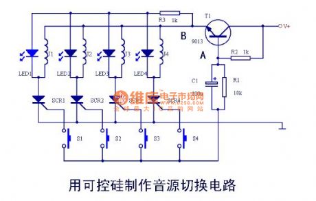
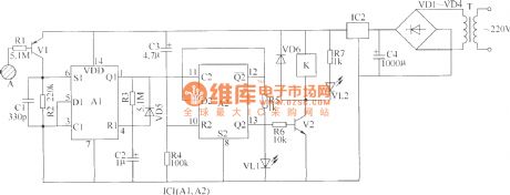
When the power is getting through, as the control pole of SCR1--SCR4 has no trigger current, so it is in the turn-off state, none of J1-J4 is taking action. If J1 pulls in, by pressing S1, the current will charges C1 through R2, point A is in a low LEV to the earth, T1 is blocked. As C1 is charged, the LEV of B is rising with the LEV of A. At that moment, the charge current of C1 is crossing the control of SCR1, so SCR is conducting, J1 is getting power and pulling in, LED1 is glowing, after S1 is released, as the effect of SCR1, J1 remains the same, C1 is discharging through R1. (View)
View full Circuit Diagram | Comments | Reading(742)
The audio control and soft switch amplifier
Published:2011/7/7 8:07:00 Author:Seven | Keyword: audio control, soft switch amplifier
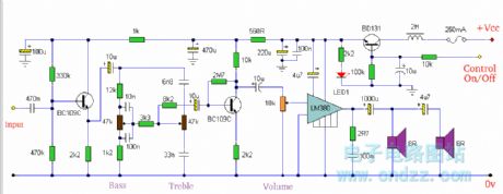
The soft switching is enabled by a BD131 transistor wired as a switch in emitter follower configuration. The collector is wired to a permanent supply voltage, the 2H series inductor serves only to filter out power supply hum. This inductor is not too important and may be omitted if the DC supply is adequately smoothed. The control voltage is applied to the BD131 base terminal, the 10u capacitor and 10k resistor having a dual purpose:-i) a gradual charge of the 10u capacitor ensures that the transistor will switch linearly from 0 volts to full supply, andii) serves as a hum filter ensuring a very smooth dc supply to the amplifier and tone controls.LED1 will light when the amplifier is on. The control voltage should ideally be 0 volts when the amplifier is off and full supply voltage when on. The LM380 is shown driving two 8 ohm loupspeakers, the load is therefore 4 ohms. The 4u7 capacitor acts as a crude crossover, lower frequencies are impeded and so this loudspeaker may be a tweeter type. (View)
View full Circuit Diagram | Comments | Reading(1002)
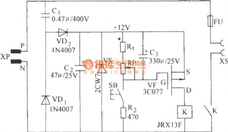
The time delay circuit with a FET
Published:2011/7/7 8:09:00 Author:Seven | Keyword: time delay circuit, FET
View full Circuit Diagram | Comments | Reading(732)
The astable circuit of direct relay drive
Published:2011/7/7 8:11:00 Author:Seven | Keyword: astable circuit, relay drive
View full Circuit Diagram | Comments | Reading(803)
The over-current precaution circuit (current limiting circuit)
Published:2011/7/7 8:27:00 Author:Seven | Keyword: over-current precaution
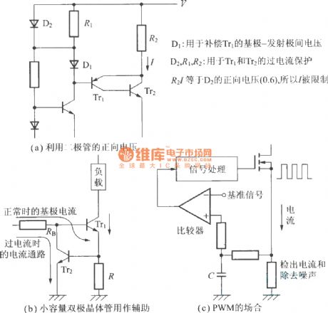
D1 is used to compensate the voltage between the base-electrode of Tr1; D2, R1 and R2 are used for over-current protection of Tr1 and Tr2; R2I is equal to the forward voltage(0.6) of D2, so it is limited.(a) the forward voltage of the diode in use(b) small volume diode as the assistance(c) the PWM spot (View)
View full Circuit Diagram | Comments | Reading(898)
The protection switch
Published:2011/7/7 7:50:00 Author:Seven | Keyword: protection switch
View full Circuit Diagram | Comments | Reading(651)
The electric switch circuit of touch type (2)
Published:2011/7/7 21:48:00 Author:Seven | Keyword: electric switch circuit, touch type
Here is to introduce an electric switch circuit composed of CMOS digital circuit, which can be used to control the lighting lamp, ventilator and other low power electric apparatus. The electric switch circuit of touch type consists of the power supply circuit, touch control input circuit, single stable trigger circuit, dual stable trigger and control executing circuit, see as the figure.
Element selectionR1~R7 are the 1/4W carbon film resistor or metal film resistor.C1 is the high frequency pottery capacitor; C2 is the Ta electrolytic capacitor or high grade aluminum electrolytic capacitor. (View)
View full Circuit Diagram | Comments | Reading(711)
The dual stable circuit with diode clamper
Published:2011/7/7 8:34:00 Author:Seven | Keyword: dual stable circuit, diode clamper
View full Circuit Diagram | Comments | Reading(886)
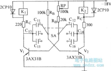
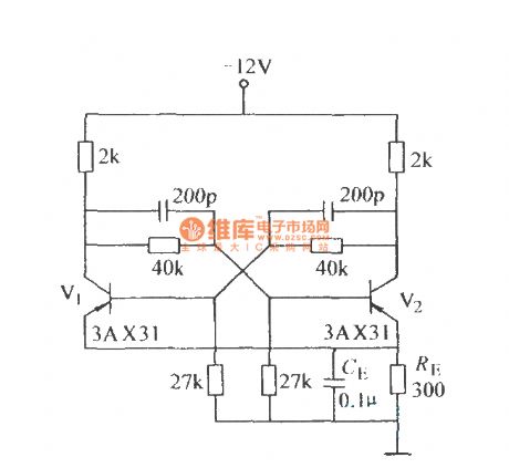
The dual stable circuit with self-bias voltage
Published:2011/7/7 8:31:00 Author:Seven | Keyword: dual stable circuit, self-bias voltage
View full Circuit Diagram | Comments | Reading(700)
The electric magnet executing circuit controlled by LED
Published:2011/7/7 8:30:00 Author:Seven | Keyword: electric magnet, executing circuit

View full Circuit Diagram | Comments | Reading(608)
Active biquad low-pass filter circuit
Published:2011/7/7 0:01:00 Author:Fiona | Keyword: Active, biquad low-pass filter
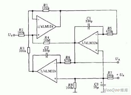
Active filter circuit is shown as above, its center frequency is1KHz, the quality factor Q = 50, gain KV = 100 (it's equal to 40dB)
(View)
View full Circuit Diagram | Comments | Reading(807)
RF power control system composed of the AD8362
Published:2011/7/6 21:24:00 Author:Christina | Keyword: RF, power control system
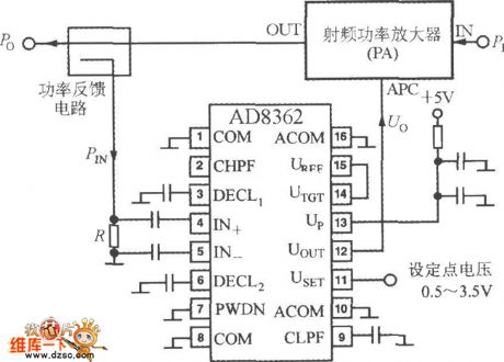
The RF power control system which is composed of the AD8362 is as shown in the figure, the pin-11 is connected with the set-point voltage USET, the voltage range is 0.5~3.5V. The controlled system is RF power amplifier (PA). You can set the input power of PA is PI, the output power is Po, the Po changes with the control voltage Vo that is added on the control port APC. You can form the control loop by using the power feedback circuit to make the output power of PA the same with the set value. PIN is the feedback power, R is the sampling resistance of the feedback power.
(View)
View full Circuit Diagram | Comments | Reading(763)
The input protection circuit of AD8362
Published:2011/7/6 21:07:00 Author:Christina | Keyword: input, protection circuit
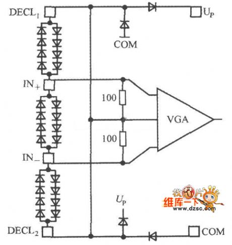
The input protection circuit of AD8362 is as shown in the figure. You can connect two groups of composite diode reverse polarity between the IN+ and IN- in parallel, so it plays the clamping protection function to avoid the damage that is caused by the instantaneous high voltage. In addition, there are the diode clamping protection circuits between the pins of DECL1 and IN+ or the IN- and DECL2.
(View)
View full Circuit Diagram | Comments | Reading(659)
Microtek MRS-1200TP scanner switching power supply circuit
Published:2011/7/6 21:52:00 Author:Christina | Keyword: Microtek, scanner, witching power supply
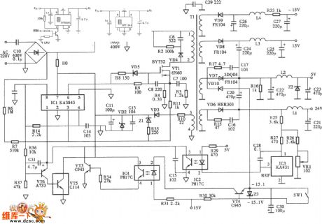
Figure:Microtek MRS-1200TP scanner switching power supply circuit
(View)
View full Circuit Diagram | Comments | Reading(3126)
The infrared detection alarm circuit
Published:2011/7/7 0:21:00 Author:qqtang | Keyword: infrared detection alarm
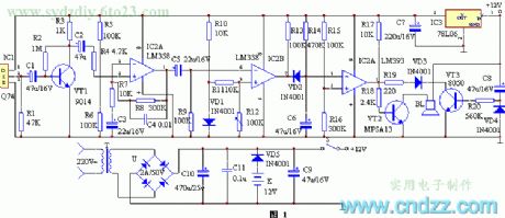
Working principles
The circuit principle is in figure 1, which consists of the infrared sensor, signal amplifier circuit, voltage comparator, time delay circuit and stereo alarm circuit, etc. When the sensor IC1 detects the infrared signal emitted from the human body, the 2-pin of IC1 is outputting a weak electric signal which is firstly amplified by the first-stage amplifier circuit composed of VT1 and so on, and then it is sent to the computing amplifier IC2 by C2 for gain expansion and low-noise amplification, at the moment, the signal output by 1-pin of IC2 is strong enough. (View)
View full Circuit Diagram | Comments | Reading(825)
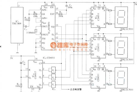
The infrared detection multi-channel alarm circuit(TDC1808/TDC1809)
Published:2011/7/7 0:31:00 Author:qqtang | Keyword: infrared detection, multi-channel alarm
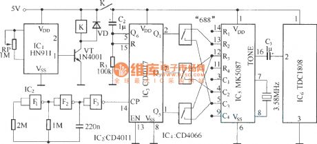
emitting circuit:
receiving circuit:
(View)
View full Circuit Diagram | Comments | Reading(688)
The microwave detection wireless alarm (S&P27)
Published:2011/7/7 0:40:00 Author:qqtang | Keyword: microwave, detection, wireless alarm

In figure (a), when the detecting circuit TWH9250 is detecting the object signal, the terminal O is outputting a low LEV, and the relay K is connected. After the emitting circuit is connected with the power supply, the address code programmed by YYH26 is amplified by S&P27A and then emitted into the sky through the aerial. The detecting circuit is used to link to the working power source of the emitter, the address code emitted by the circuit represents the position of the emitter. In figure (b) is the multi-channel reception alarm circuit. (View)
View full Circuit Diagram | Comments | Reading(1074)
The microwave language burglarproof alarm
Published:2011/7/7 0:12:00 Author:qqtang | Keyword: language burglarproof alarm
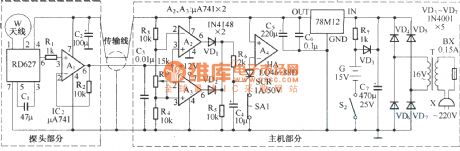
The microwave language burglarproof alarm is fitted in homes, shops, storerooms, orchestras and so on. When someone is going into the alert area, it will make the sound of catch the thief . To prevent it from being broken, there are functions of breakdown alarm and AC/DC power auto shift in it. The principle of the circuit is shown in the figure. The alarm consists of the probe and the host. The probe consists of the microwave sensing module RD627 and op-amp A1, the output signal of RD627 is amplified by A1 and then connected with the host by the dual chip shield cable.
(View)
View full Circuit Diagram | Comments | Reading(728)
The pocket-sized money drawer burglarproof alarm circuit
Published:2011/7/6 23:53:00 Author:qqtang | Keyword: pocket-sized, money drawer, burglarproof alarm
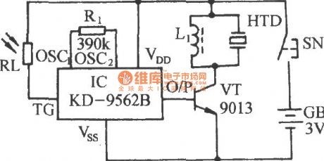
The figured circuit is assembled on the base of a light control alarm analog sound integrated circuit KD-9562B. Its size is small, just like a watch box, the number of the external elements is 5, which can be used in the drawer or wallet as the burglarproof alarm. (View)
View full Circuit Diagram | Comments | Reading(965)
The new style flashing alarm integrated application circuit
Published:2011/7/6 20:55:00 Author:qqtang | Keyword: flashing alarm, integrated application circuit
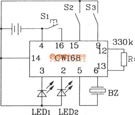
The new style flashing alarm integrated application circuit R1 is an external resistor of the internal oscillator, by changing the resistance of R1, the frequency of the internal oscillator in IC can be changed, when R1=330kΩ, the output flashing frequency of IC is 4Hz, and the IC will stop working in 16s after it is triggered. To strengthen the sound effect, a power triode can be connected with the output terminal, which can drive the loudspeaker play back. Besides, CW168 can be triggered by all kinds of control circuits, so the auto control can be fulfilled. (View)
View full Circuit Diagram | Comments | Reading(639)
| Pages:216/312 At 20201202203204205206207208209210211212213214215216217218219220Under 20 |
Circuit Categories
power supply circuit
Amplifier Circuit
Basic Circuit
LED and Light Circuit
Sensor Circuit
Signal Processing
Electrical Equipment Circuit
Control Circuit
Remote Control Circuit
A/D-D/A Converter Circuit
Audio Circuit
Measuring and Test Circuit
Communication Circuit
Computer-Related Circuit
555 Circuit
Automotive Circuit
Repairing Circuit