
Index 48
A multifunctional pump control circuit
Published:2012/11/16 2:52:00 Author:Ecco | Keyword: multifunctional pump control
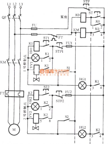
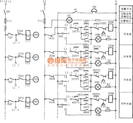
Many high-power devices need circulating cooling water for cooling. When it has many cooling equipment units, you can install a shared water pump using multifunctional control method, then each operating point can start pump separately, and they can separately stop pump, when any one is using water, it also can prevent other point from turning off the pumps.
(View)
View full Circuit Diagram | Comments | Reading(5614)
Gate Alarm
Published:2012/11/15 21:18:00 Author:muriel | Keyword: Gate Alarm
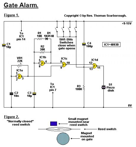
A cheap and simple gate alarm made from a single CMOS Integrated Circuit.Circuit NotesFigure 1 represents a cheap and simple Gate Alarm, that is intended to run off a small universal AC-DC power supply.
IC1a is a fast oscillator, and IC1b a slow oscillator, which are combined through IC1c to emit a high pip-pip-pip warning sound when a gate (or window, etc.) is opened. The circuit is intended not so much to sound like a siren or warning device, but rather to give the impression: You have been noticed. R1 and D1 may be omitted, and the value of R2 perhaps reduced, to make the Gate Alarm sound more like a warning device. VR1 adjusts the frequency of the sound emitted.
IC1d is a timer which causes the Gate Alarm to emit some 20 to 30 further pips after the gate has been closed again, before it falls silent, as if to say: I'm more clever than a simple on-off device. Piezo disk S1 may be replaced with a LED if desired, the LED being wired in series with a 1K resistor.
Figure 2 shows how an ordinary reed switch may be converted to close (a normally closed switch) when the gate is opened. A continuity tester makes the work easy. Note that many reed switches are delicate, and therefore wires which are soldered to the reed switch should not be flexed at all near the switch. Other types of switches, such as microswitches, may also be used. (View)
View full Circuit Diagram | Comments | Reading(867)
VHF/UHF TV Modulator
Published:2012/11/15 21:10:00 Author:muriel | Keyword: VHF/UHF , TV , Modulator
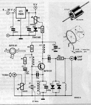
Simple oscillator that generates a frequency in the VHF or UHF region. The oscillator is modulated with the video signal and the modulated carrier wave thus generated is fed into the TV set's aerial input via a cable. Then all that remains to do is tune the TV to the correct frequency. (View)
View full Circuit Diagram | Comments | Reading(3688)
VHF/UHF Prescaler
Published:2012/11/15 21:10:00 Author:muriel | Keyword: VHF/UHF, Prescaler
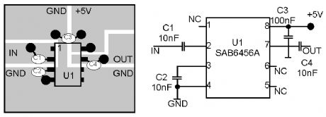
The recommended Prescaler is ridiculously simple. It consists of just one IC, a TV tuner prescaler, the Philips SAB6456A, which can divide by 64 or by 256. This chip is widely available both new and in the surplus market at much lower prices than conventional divide by 10 prescalers. (View)
View full Circuit Diagram | Comments | Reading(2429)
Remote control using VHF modules
Published:2012/11/15 0:45:00 Author:muriel | Keyword: Remote control, VHF modules
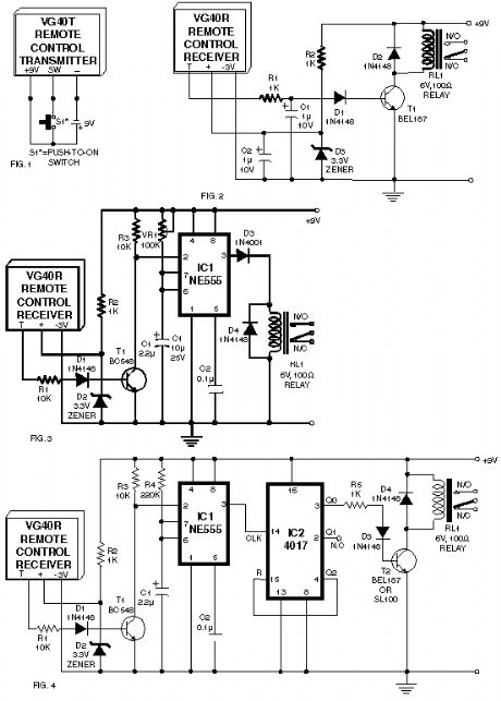
A few designs for remote control switches, using VG40T and VG40R remote control pair, are shown here. The miniature transmitter module shown in Fig. 1, which just measures 34 mm x 29 mm x 10 mm, can be used to operate all remote control receiver-cum-switch combinations described in this project. A compact 9-volt PP3 battery can be used with the transmitter. It can transmit signals up to 15 metres without any aerial. The operating frequency of the transmitter is 300 MHz. The following circuits, using VG40R remote control receiver module measuring 45 mm x 21 mm x 13 mm, can be used to: (a) activate a relay momentarily, (b) activate a relay for a preset period, (c) switch on and switch off a load. (View)
View full Circuit Diagram | Comments | Reading(1252)
Radio Remote Control using DTMF
Published:2012/11/15 0:44:00 Author:muriel | Keyword: Radio, Remote Control , DTMF
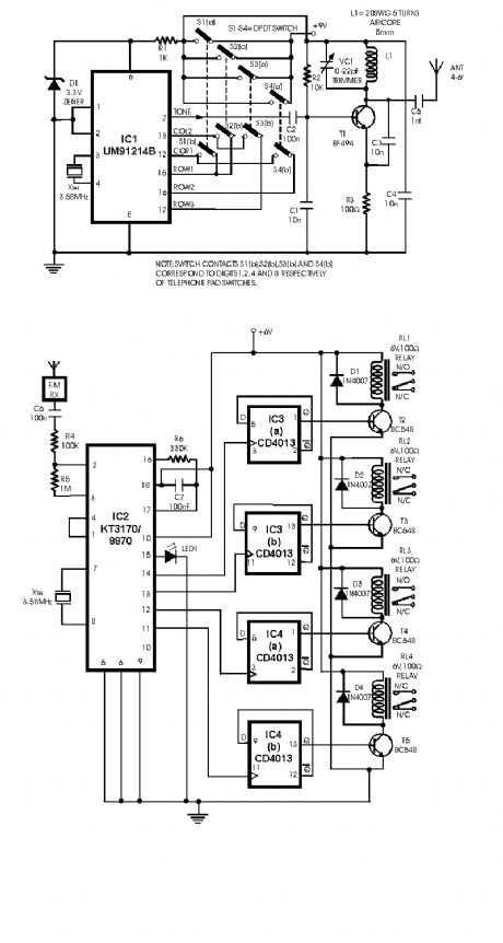
Here is a circuit of a remote control unit which makes use of the radio frequency signals to control various electrical appliances. This remote control unit has 4 channels which can be easily extended to 12. This circuit differs from similar circuits in view of its simplicity and a totally different concept of generating the control signals. Usually remote control circuits make use of infrared light to transmit control signals. Their use is thus limited to a very confined area and line-of-sight. However, this circuit makes use of radio frequency to transmit the control signals and hence it can be used for control from almost anywhere in the house.
Here we make use of DTMF (dual-tone multi frequency) signals (used in telephones to dial the digits) as the control codes. The DTMF tones are used for frequency modulation of the carrier. At the receiver unit, these frequency modulated signals are intercepted to obtain DTMF tones at the speaker terminals. This DTMF signal is connected to a DTMF-to-BCD converter whose BCD output is used to switch-on and switch-off various electrical appliances.
(View)
View full Circuit Diagram | Comments | Reading(1465)
The neutral point voltage open phase voltage relay protection circuit
Published:2012/11/14 19:52:00 Author:Ecco | Keyword: neutral point, voltage, open phase, voltage relay, protection
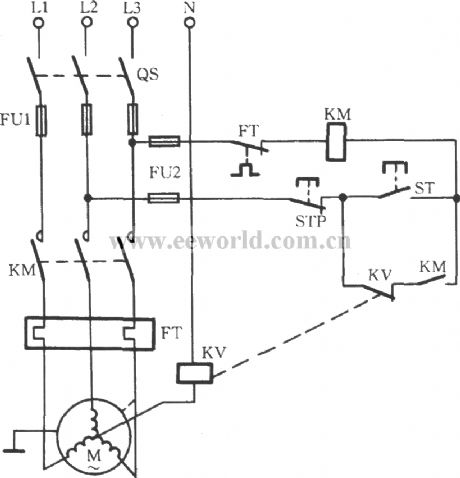
When any one phase of the motor three-phase power supply loses power, if the motor uses Y connection, wherein the neutral point (midpoint) voltage will be significantly improved. Therefore, the midpoint voltage can be used as off -phase fault signal. As shown in figure, the circuit uses voltage relay for protection device.
(View)
View full Circuit Diagram | Comments | Reading(1917)
Resistance-capacitance phase protection circuit
Published:2012/11/14 19:34:00 Author:Ecco | Keyword: Resistance-capacitance , phase protection
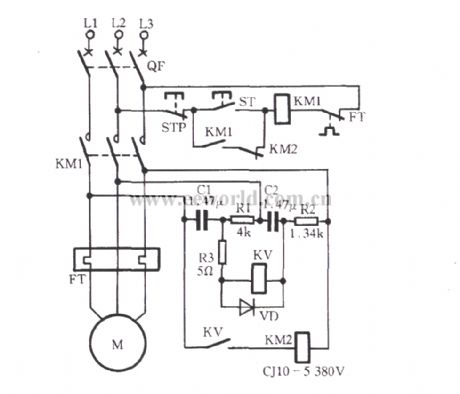
The circuit shown in Figure uses negative sequence voltage generated by unbalanced three-phase power for phase-failure protection. When the three-phase power is symmetric and line voltage has mutual lag 120°electrical angle, the voltage across the relay KV voltage is 0V, so KV has no action. When the three-phase power loses a phase, the voltage is applied to the ends of the coil, KV pulls in, and its normally open contact action to turn on KM2 coil loop, then the normally closed contact KM2 action, KM1 cuts the power supply of motor M.
(View)
View full Circuit Diagram | Comments | Reading(3097)
555 automatically pushed coal timing control circuit
Published:2012/11/14 20:07:00 Author:Ecco | Keyword: 555, automatically pushed coal , timing control
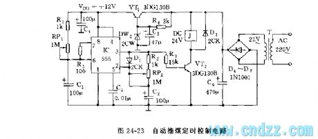
As shown in Figure 24-23, the control circuit is composed of adjustable buck power and multivibrator with adjustable duty cycle and VT2 relay control circuit. R1, RP1 and C1 form charging circuit.
(View)
View full Circuit Diagram | Comments | Reading(926)
△ connection motor phase failure voltage relay protection circuit
Published:2012/11/14 20:18:00 Author:Ecco | Keyword: △ connection, motor , phase failure, voltage relay protection
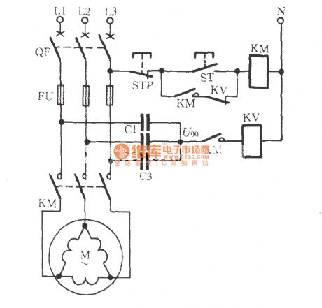
For △ connection motor, you must add neutral point, that is, three Y-shaped capacitors are connected ( impedance element ) with the motor in parallel, then the neutral point of Y shape is connected to the relay protection element, and it is shown in figure. During normal operation of the motor phase power supply, the neutral point voltage U00 is typically less than 10V.
(View)
View full Circuit Diagram | Comments | Reading(1929)
Multi-function electric fan control circuit with crickets sound using PT2124
Published:2012/11/13 20:13:00 Author:Ecco | Keyword: Multi-function , electric fan , control circuit , crickets sound
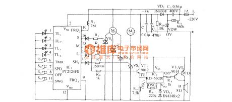
As shown in the figure, when you press speed key to start the fan, in each case, it is operates with stroke. M-end (15 feet) outputs drive signal which is added to VT1 (PNP tube)'s b pole by R6 to make VT1 get conduction, e pole's low level signal can triggers IC2. IC2 uses animal voice simulation integrated circuit KD-56020, once it is triggered, the animal voice is broadcasted as signal which is amplified by Darlington-level with VT2 and VT3-l, then it drivies speakers b to emit sound.
(View)
View full Circuit Diagram | Comments | Reading(1004)
Simulated natural wind fan control circuit accompanied by the waves sound
Published:2012/11/13 20:25:00 Author:Ecco | Keyword: Simulated natural wind, fan control, waves sound
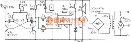
It consists of a variable frequency multivibrator, relay control circuit, analog waves sound circuit and AC buck rectifier circuit. Ordinary fan is configurated with the control circuit which can allow wind to be strong or weak and accompanied by realistic sound of the waves. People will have natural feelings when they are enjoying the cool wind. VT1, VT2, C1, C2, R1~R3 and RP1 form a multivibrator.
(View)
View full Circuit Diagram | Comments | Reading(799)
Automatically input control circuit of the pump station preparedness
Published:2012/11/13 20:38:00 Author:Ecco | Keyword: Automatically input, control , pump station preparedness
Plant cooling water pump house often needs to configure multiple pumps and equipment units ( one of them is used as standby pump ). When one pump stops due to a fault, standby pump will be automatically prepared and put into operation, and the number of pumps is decided by the amount of water.
(View)
View full Circuit Diagram | Comments | Reading(1456)
EOCR motor protection circuit
Published:2012/11/12 20:27:00 Author:Ecco | Keyword: EOCR , motor protection
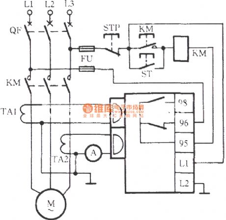
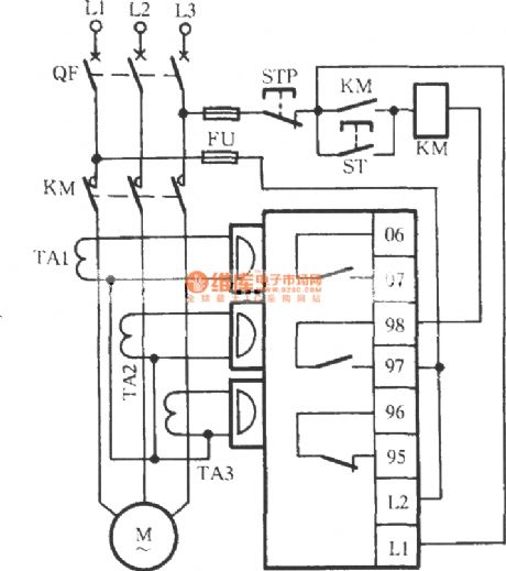
EOCR is Korea SAMWHA 's new motor protector with a microprocessor, , there are two popular kinds of EOCR-SS type EOCR-3DD in the market. Wiring diagram is shown in Figure 2.
(View)
View full Circuit Diagram | Comments | Reading(2555)
The motor overheating and influent protection circuit
Published:2012/11/12 20:39:00 Author:Ecco | Keyword: motor , overheating , influent protection
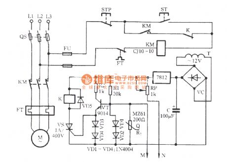
Before the burned-out motor damage, its winding temperature rises high; in many occasions, motor is easily bilging, resulting in burned. The circuit is shown in Figure. It can prevent overheating influent accidents. RT is a positive temperature coefficient thermistor (PTC); M, N are plastic insulated wires which are closed and buried in the motor stator windings, and their heads are stripped, they are used for detecting the motor inlet.
(View)
View full Circuit Diagram | Comments | Reading(3420)
The Chunhua cleaner electronic speed control circuit
Published:2012/11/12 20:57:00 Author:Ecco | Keyword: Chunhua , cleaner , electronic , speed control
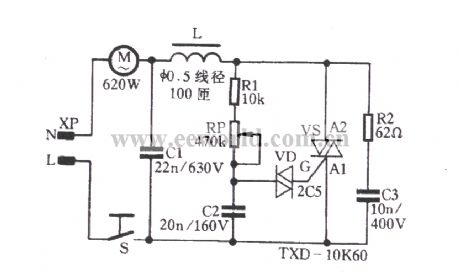
This circuit is composed of the following two parts: (1) phase shifting circuit. R1, RP, C2 constitute a phase shifting circuit. When the voltage VC2 across C2 gets the breakover voltage of trigger diode VD, VD gets conduction, C2 discharges, three-terminal bidirectional thyristor VS can control of pole flow pulse current is triggered by conduction. Adjusting potentiometer RP can adjust the phase of the gate pulse and change the conduction angle of VS, thereby adjusting the motor voltage and controlling the rotational speed of the M.
(View)
View full Circuit Diagram | Comments | Reading(1237)
Garden Timer with Remote control
Published:2012/11/9 20:31:00 Author:muriel | Keyword: Garden Timer, Remote control
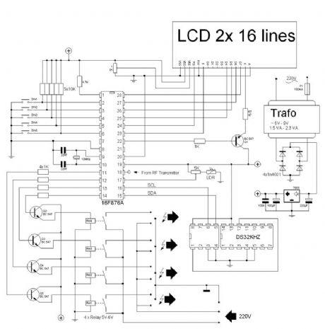
Few years ago we control the lights in the garden with a automatic-timer-switch, very nice but when the evening gets longer or shorter we had to adapt the timer each week. In that time I came in contact with programming microprocessors so my first project was born. The first garden timer was a simple 1 output. The timing was controlled by the PIC and every month I had to change the minutes. So back to the table and design the second garden timer able to control 3 relays - left, mid and right side of the garden. It provided also 4 modes: � always off � always on � from dusk to dawn � from dusk to timer and the timing was dedicated to a RTC DS1307. (View)
View full Circuit Diagram | Comments | Reading(1180)
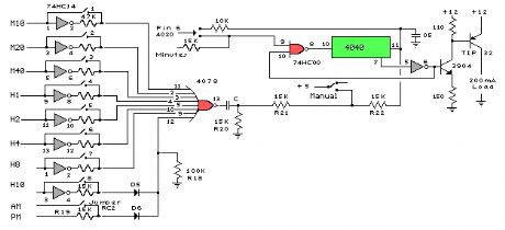
Clock Timer Circuits
Published:2012/11/9 20:27:00 Author:muriel | Keyword: Clock Timer Circuits
View full Circuit Diagram | Comments | Reading(735)
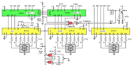
Clock Display Circuits
Published:2012/11/9 20:26:00 Author:muriel | Keyword: Clock Display Circuits
View full Circuit Diagram | Comments | Reading(1011)
Basic Clock Circuit
Published:2012/11/9 20:25:00 Author:muriel | Keyword: Basic Clock Circuit
View full Circuit Diagram | Comments | Reading(883)
| Pages:48/312 At 204142434445464748495051525354555657585960Under 20 |
Circuit Categories
power supply circuit
Amplifier Circuit
Basic Circuit
LED and Light Circuit
Sensor Circuit
Signal Processing
Electrical Equipment Circuit
Control Circuit
Remote Control Circuit
A/D-D/A Converter Circuit
Audio Circuit
Measuring and Test Circuit
Communication Circuit
Computer-Related Circuit
555 Circuit
Automotive Circuit
Repairing Circuit