
Circuit Diagram
Index 1835
FM transmitter principle circuit
Published:2011/5/23 21:49:00 Author:John | Keyword: FM transmitter
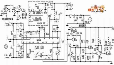
FM transmitter principle circuit is shown below.
(View)
View full Circuit Diagram | Comments | Reading(965)
Aihua CFXB double light insulation automatic rice cooker circuit
Published:2011/5/24 0:15:00 Author:John | Keyword: automatic rice cooker
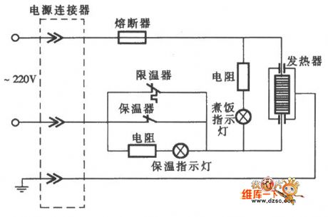
Aihua CFXB double light insulation automatic rice cooker circuit is shown below.
(View)
View full Circuit Diagram | Comments | Reading(1634)
Microwave circuit
Published:2011/5/23 23:28:00 Author:John | Keyword: Microwave
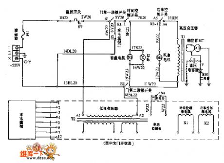
Microwave circuit is shown below.
(View)
View full Circuit Diagram | Comments | Reading(1530)
555 photo amplification automatic metering timer circuit
Published:2011/5/23 4:03:00 Author:TaoXi | Keyword: photo amplification, automatic metering, timer
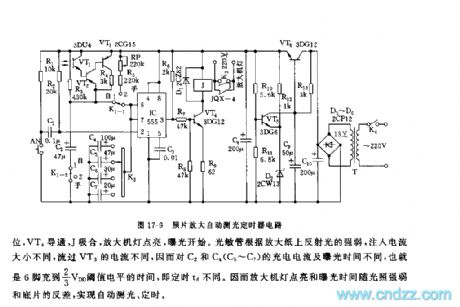
As the figure 17-9 shows, the timer is composed of the photosensitive sensor head, the 555 and the C2, C4~C7.etc. And this circuit can be used in wide range of applications such as the photo amplification automatic metering timer.
The photosensitive sensor uses the phototransistor 3DU type, when K1 is in the position of AE 1 , you press AN, the 555 sets, VT4 conducts, J closes, and the amplifier light turns on, the exposure starts. The photodiode injects different kinds of current to VT3 according to the strength of the enlarging paper's reflected light. So the time of pin-6 charges to the 2/3VDD threshold level is different.
(View)
View full Circuit Diagram | Comments | Reading(576)
555 photographic exposure timer circuit
Published:2011/5/23 5:30:00 Author:TaoXi | Keyword: photographic, exposure, timer circuit
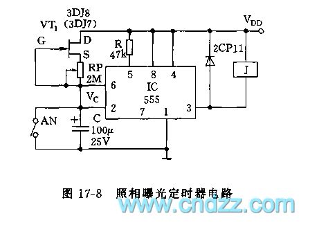
As the figure 17-8 shows, the timer uses the 555 as the core. If you press switch AN, the timing begins. You need to press AN to set the 555's trigger port,pin-3 has the high electrical level, the normally closed contact point of the relay will turn on the expose lamp. Then the C is charged through VT1 and RP. In order to make the charging voltage to keep the linear growth, we use the MOSFET 3DJ8 for the cross-flow charging. When C's charging voltage is higher than pin-6's threshold level 2/3VDD, 555 resets, pin-3 has the low electrical level.
(View)
View full Circuit Diagram | Comments | Reading(883)
555 household automatic lighting switch
Published:2011/5/22 18:57:00 Author:TaoXi | Keyword: household, automatic, lighting switch
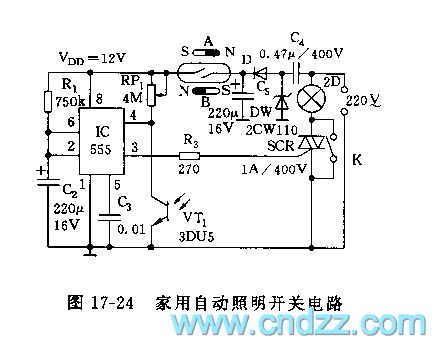
As the figure 17-24 shows, you can use the photosensitive sensor and the magnetic switch to control 555's trigger state and power supply, at night, this circuit can automatically open and auto-off delay.
The city electricity is stepped down and rectified by the circuit, then it becomes the 12V voltage to supply the 555. The controllable trigger delay circuit is composed of the 555 and R1,C2,VT1, RP1. In the day time, the VT1(3DU5) is in the low resistance state because of the illumination, so the 555's pin-4 has the low electrical level (<0.7V), the 555 is forced to reset, pin-3 has the low electrical level, SCR cuts off.
(View)
View full Circuit Diagram | Comments | Reading(923)
555 acute coronary artery blood-supply insufficiency alarm circuit
Published:2011/5/24 2:54:00 Author:TaoXi | Keyword: acute coronary artery, blood-supply, insufficiency, alarm circuit
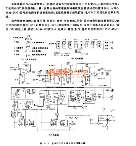
The acute or chronic myocardial infarction disease's omen is the acute coronary artery blood-supply insufficiency, and the heart waves obvious variation. The principle of the alarm circuit: changes the amplitude variation into the width variation.
In the circuit, the IC1 is the monostable trigger, the timing time t2=1 minute; IC2 is the monostable trigger, the timing time t3=2 minutes; it controls the on-off of the IC9 and IC10 alarm circuit's power supply voltage. IC9 is the low frequency astable multivibrator, it produces the 1Hz square-wave signal to control the multivibrator (the oscillation frequency is 1000Hz) IC10's control port pin-5 to produce the variable tones audio alarm signal.
(View)
View full Circuit Diagram | Comments | Reading(1041)
555 breath monitor circuit
Published:2011/5/23 20:04:00 Author:TaoXi | Keyword: breath, monitor
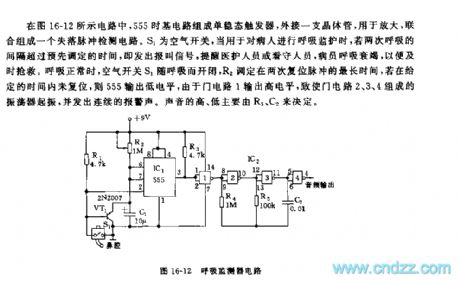
As the figure 16-12 shows, the monostable trigger is composed of the 555 time base circuit, and this circuit connects with a external transistor, the lost pulse detection circuit is composed of the external transistor and the monostable trigger. S1 is the air switch. When this circuit is used in the patient's breath monitor application, if the interval of the two respiratories overs the pre-set time, this circuit sends out the alarm signal to remind the health care workers or guards. When the breath is normal, the air switch S1 opens and closes with the breath, R2 is set in the longest time of the twice reset pulse, if it is not resetting in a given period of time, 555 will output the low electrical level.
(View)
View full Circuit Diagram | Comments | Reading(1218)
555 electronic timing, hypnosis and massager circuit
Published:2011/5/23 21:12:00 Author:TaoXi | Keyword: electronic, timing, hypnosis, massager
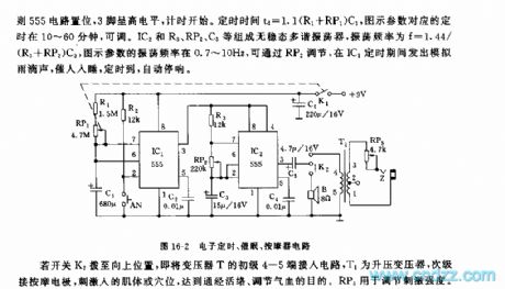
As the figure 16-2 shows, the monostable timing circuit is composed of the IC1 and R1,RP1,C1, An is the timing start-up button, if you press AN, the 555 circuit sets, pin-3 has the high electrical level, and the timing begins. The timing time td=1.1(R1+RP1)C1, the corresponding timing time of the figure parameters is between 10 to 60 minutes, and it is adjustable. The astable multivibrator is composed of the IC2 and R3,RP2,C3, the oscillation frequency f=1.44/(R3+RP2)C3, the figure parameters' oscillation frequency is 0.7-10Hz, you can adjust it by RP2, during the IC1's timing time, this circuit sends out the voice of raindrop to encourage people to sleep, when the timing time is up, it automatically stops the sound.
(View)
View full Circuit Diagram | Comments | Reading(720)
555 hepatitis germs disinfector control circuit
Published:2011/5/23 20:15:00 Author:TaoXi | Keyword: hepatitis, germs, disinfector, control circuit
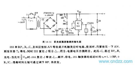
As the figure 16-10 shows, this disinfector control circuit is composed of the step-down rectifier circuit (VDD=+6V), the 555 boot timing circuit and the control circuit. It can be used to control the timing time of the sodium hypochlorite production.
The boot trigger timing circuit is composed of the 555, RP1,R1,C1 and the double-deck button AN. When you are using it, press AN, the transformer T1 gets the power, and 555 sets, J and J1-1 close, the power supply voltage self-locking closes. And then, C1 is charged through RP1 and R1, when C1 is charged to 2/3VDD, 555 resets, J releases, J1-1 cuts off, there is no power supply. The 555 trigger's delay time td=1.1(RP1+R1)C1, you can change the length of the sterilization time by adjusting RP1.
(View)
View full Circuit Diagram | Comments | Reading(562)
The 555 electronic fishing game circuit
Published:2011/5/25 3:26:00 Author:nelly | Keyword: electron, fishing game, circuit
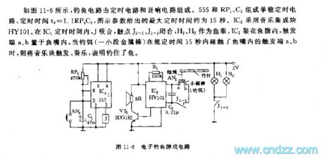
As shown on the figure 11-6, the fishing circuit consists of timing circuit and audio circuit. 555, RP1 and C1 make up the single shot circuit. The definite time: td=1.1RP1C1. The maximal definite time given by the figure is 15s.IC2 adopts the muisc integrated block HY101. In the IC1's definite time, J is pull-in, the contact J1-1 and J1-2 is closed, H1 and H2 are treated as fish-eye. IC2 is sacked in the fish belly, the a and b is loaded in the fish mouth,If the metal bar in 15s contacts the a and b in the fish mouth, the music block will play up which represents the fish is catched.
(View)
View full Circuit Diagram | Comments | Reading(1554)
The 555 electronic touching game circuit
Published:2011/5/26 4:47:00 Author:nelly | Keyword: electron, touching, game
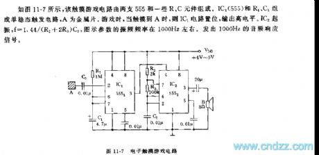
As shown on the figure 11-7, two pieces of the 555 and some components make up this touching game's circuit.The Monostable trigger circuit consists of the 555 IC1, R1 and C1. A is bimetallic strip. When touching the A in playing games, the IC1 will be set and output high power level.The IC2 will be onset, f=1.44/(R2+2R3)C2, the vibration frequency on the figure is about 1000Hz. (View)
View full Circuit Diagram | Comments | Reading(789)
AN8812K-the integrated servo-driven circuit
Published:2011/5/18 0:17:00 Author:Borg | Keyword: servo-driven, integrated
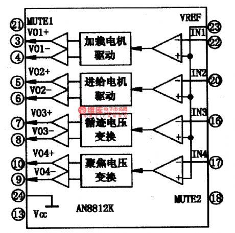
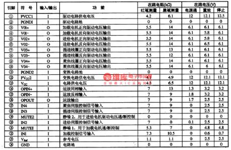
AN8812K is an integrated servo-driven circuit produced by Panasonic Corp., Japan, which is used in DVD core as the laser head servo driver.1.the internal circuitAN8812K contains 4-channel servo driven circuits, whose internal circuit is listed in Figure 1.
Figure 1 the internal circuit of AN8812K2.pin functions and dataAN8812K is in 24-lead dual line package, whose pin functions and data are listed in Table 1, the data come from tests on TCL DVD-250O.
(View)
View full Circuit Diagram | Comments | Reading(661)
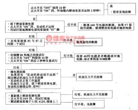
The oil pump relay circuit of Daewoo-ESPERO
Published:2011/5/18 21:03:00 Author:Borg | Keyword: oil pump relay, Daewoo-ESPERO
6.The diagnosis on the fault of rotating engine without runningThe so-called rotating engine without running means that the engine can rotate driven by the stater but can not automatically run. Before we judge the fault, we should make sure the battery has enough power, and the stating speed of the engine is normal, there is enough oil in the box. The circuit is shown in Figure 13, and the diagnosis course marks of * are introduced as follows.*1 the lighting of repair the engine immediately indicator means the power supply voltage and igniting voltage of 5V have been transmitted to ECM.
(View)
View full Circuit Diagram | Comments | Reading(799)
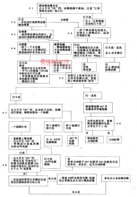
The fault diagnosis circuit of Daewoo ESPERO fuel system
Published:2011/5/18 4:35:00 Author:Borg | Keyword: diagnosis circuit, fuel system
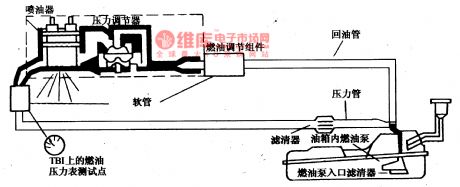
When the switch is on, start the engine and it begins to run, then ECM will receive the reference pulse from HEI electricity distributor,If there is no reference pulse, ECM will shut down the oil pump in 2 seconds after the igniting switch is on. The fuel pump will give the throttle injector a pressure of 62~9OkPa(9~13psi), and the spare oil will go back to the oil box.The fuel pump test pin is on the left side of the engine cylinder, and when the engine is stalling, it will impose a battery voltage on the pin so that the pump will work temporarily.
(View)
View full Circuit Diagram | Comments | Reading(1343)
AN8481SQ-the integrated circuit of 3-spindle motor and loading motor drives
Published:2011/5/18 4:08:00 Author:Borg | Keyword: integrated circuit, motor drives
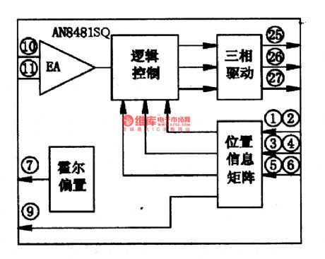
1.function featuresAN8481SQ is supposed to convert the spindle servo error control signals into 3-phase drive voltages to drive the motor, whose internal circuit is shown is Figure 1.
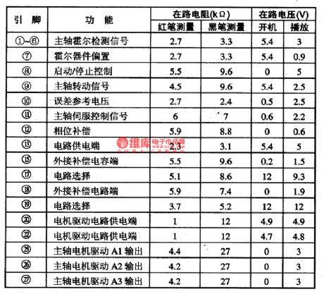
2.pin functions and dataAN8481SQ has a function of overheat protection, which is in flat 28-lead package with cooling fins. It is used in GD2O0l DVD player of Hitachi, whose pin functions and data are listed in Table 1. In the table, the pins of (21), (23) and (24) are empty, (14) and (16) are earth terminals, (28) is the earth terminal of the drive circuit.
(View)
View full Circuit Diagram | Comments | Reading(517)
The idle speed improving control circuit of Tianjin Xiali TJ710OE
Published:2011/5/20 4:13:00 Author:Borg | Keyword: idle speed, control circuit, Tianjin Xiali
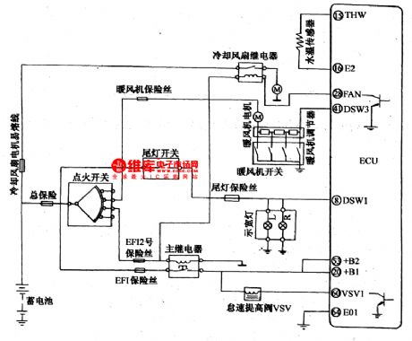
When the engine begins to run but it was not hot enough and the electricity load is raising, such as the time after the warm air fan switch, cooling fan relay and tail lamp switches are connected, meanwhile the cutting/offering oil injector is working asynchronously, the signals are sent to ECU in the form of switch volume or analog volume signals, and the ECU will order VSVI terminals to connect with the ground, so that the idling speed is raised, and the magnetic valve(VSV) allows some air to flow in the balance box(not through the throttle).
(View)
View full Circuit Diagram | Comments | Reading(600)
The control circuit of shutting down the air-conditioner while accelerating of Tianjin Xiali TJ7100F
Published:2011/5/20 3:57:00 Author:Borg | Keyword: control circuit, air-conditioner, accelerating
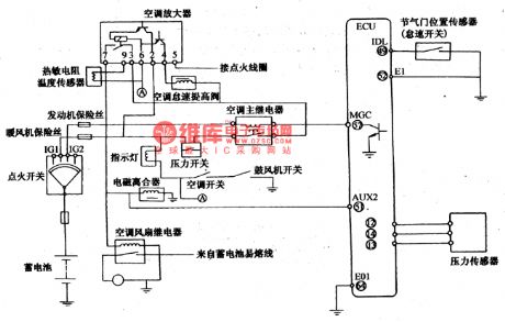
When the car accelerates at the idling speed, the switch shifts from off to on, then the MAP under the relative rotating speed reaches the regulated value. When engaging overtaking acceleration, the throttle opens wider, when the admission tube pressure and change ratio are higher than the regulated values, these signals will give orders after they have been processed by ECM, then MGC terminals connect with the earth, and the relay cuts off the power supply mainstream of the air-conditioning amplifier.
(View)
View full Circuit Diagram | Comments | Reading(482)
The igniting advance angle control circuit of Tianjin Xiali TJ7100F
Published:2011/5/20 4:31:00 Author:Borg | Keyword: advance angle, control circuit, Tianjin Xiali
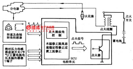
When the engine starts to run, the admission tube pressure is not stable,so it can not decide the advance angle, that's why we use a certain igniting advance angle. The angle is decided by the marks of crankshaft top pneumatic cam shaft, middle axis with toothed belt and electricity distributor, the value of the angle is 5°and 2°/800r/min。Apart from the basic igniting advance angle changes with the engine rotating speed and admission pressure, there are some modifying sectors, which are water temperature modification, idle speed-steady modification and transitional working condition modification.
(View)
View full Circuit Diagram | Comments | Reading(502)
The computer ECU function circuit of Xiali EFI TJ37100E
Published:2011/5/19 22:26:00 Author:Borg | Keyword: ECU, function circuit, Xiali
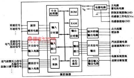
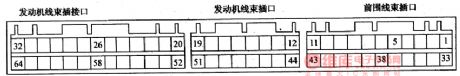
Figure 1 indicates the terminal position sequence of the computer outlet, the English code of each terminal has a certain meaning, see as Figure 2. And Table 4 illustrates the computer control function. Table 5 shows the functions and characters of the main executing components of the electronic control system.
Figure 1. the function circuit of computer ECU
(View)
View full Circuit Diagram | Comments | Reading(673)
| Pages:1835/2234 At 2018211822182318241825182618271828182918301831183218331834183518361837183818391840Under 20 |
Circuit Categories
power supply circuit
Amplifier Circuit
Basic Circuit
LED and Light Circuit
Sensor Circuit
Signal Processing
Electrical Equipment Circuit
Control Circuit
Remote Control Circuit
A/D-D/A Converter Circuit
Audio Circuit
Measuring and Test Circuit
Communication Circuit
Computer-Related Circuit
555 Circuit
Automotive Circuit
Repairing Circuit