
Circuit Diagram
Index 1841
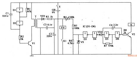
switch delay circuit
Published:2011/5/20 5:29:00 Author:chopper | Keyword: switch delay
View full Circuit Diagram | Comments | Reading(661)
mainboard of air conditioning circuit
Published:2011/5/20 5:31:00 Author:chopper | Keyword: mainboard, air conditioning
View full Circuit Diagram | Comments | Reading(657)
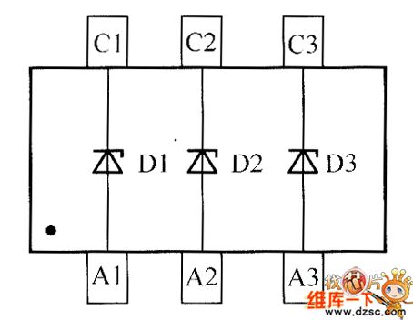
crystal diode DDZX9696TS internal circuit
Published:2011/5/20 5:34:00 Author:chopper | Keyword: internal circuit

View full Circuit Diagram | Comments | Reading(664)
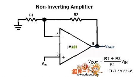
noninverting amplifier circuit
Published:2011/5/20 5:37:00 Author:chopper | Keyword: noninverting, amplifier
View full Circuit Diagram | Comments | Reading(651)
Wireless hands-free telephone system circuit
Published:2011/5/20 5:38:00 Author:chopper | Keyword: Wireless, hands-free telephone
View full Circuit Diagram | Comments | Reading(1370)
crystal diode DDZX9694TS internal circuit
Published:2011/5/20 5:40:00 Author:chopper | Keyword: crystal diode, internal circuit
View full Circuit Diagram | Comments | Reading(602)
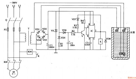
Agricultural Automatic Water Feeder (10)
Published:2011/5/22 20:19:00 Author:Sue | Keyword: Agricultural, Automatic, Water Feeder
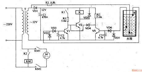
When the level is lower than c, V1 V3 are disconnected and +12V voltage is put on V2, making V2 connected.K is connected and KM begins to work. M begins to feed water.
When the level reaches C, V3 has a low level and is connected. Its integrated electrode becomes low level. VD4 is disconnected and K1 is connected. M keeps on working.
When the level reaches b, V1 has a high level and is connected. Its integrated electrode becomes low level. V2 is disconnected and K is released. M stops working . When the level is lower than the lowest level, M begins to feed water again. (View)
View full Circuit Diagram | Comments | Reading(558)
Agricultural Automatic Water Feeder (9)
Published:2011/5/22 20:13:00 Author:Sue | Keyword: Agricultural, Automatic, Water Feeder
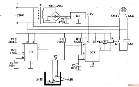
When the multivibrator begins to work, IC2's 3 pin outputs oscillator signals. When the level is lower than b, IC3's 2 pin has high level and 3 pin has low level. K is connected and K1 is connected. M begins to work. K's K2 is disconnected.
When the level is between a and b, but lower than c, K2 is disconnected and IC3's 2 pin has high level. M is still working. When the level is higher than c, IC2's 3 pin will output low level pulse, which will be put on to 2 pin. 3 pin becomes high level and K is released. K1 is disconnected and M stops working.
When the level is between a and b, K2 is disconnected and M doesn't work. When the level is lower than a,b, IC3's 2 pin becomes high level and 3 pin has low level. M begins to work again. (View)
View full Circuit Diagram | Comments | Reading(528)
Agricultural Automatic Water Feeder (8)
Published:2011/5/22 20:05:00 Author:Sue | Keyword: Agricultural, Automatic, Water Feeder

When S is on, IC's 2 pin and 6 pin have low level and 3 pin outputs high level. V2 is connected and K is connected. VL2 is illuminated. When C2 finishes charging, IC's 2 pin becomes high level, but its 6 pin is still low level. 3 pin is high level and YV is still working.
When the water tank is full, IC's 6 pin is low level and 3 pin has low level. V2 is disconnected and K is released. YV stops working and VL3 is illuminated. At the same time, V1 is connected and VL1 is illuminated, indicating that the water tank is full. (View)
View full Circuit Diagram | Comments | Reading(558)
Agricultural Automatic Water Feeder (7)
Published:2011/5/22 20:00:00 Author:Sue | Keyword: Agricultural Automatic Water Feeder
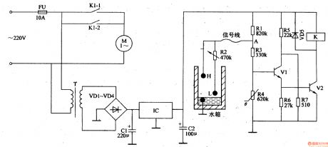
When the power is on and the level is lower than L, A’s level is highest and V1 V2 are connected. K is connected and K2 K1 are connected. M begins to feed water.
When the level is higher than H, A’s voltage is reduced to 0.2-0.3V.V1 and V 2 are disconnected. K is released and M stops working. When the level is lower than L, V1 and V2 are connected again and M begins to feed water again. (View)
View full Circuit Diagram | Comments | Reading(550)
Agricultural Automatic Water Feeder (6)
Published:2011/5/22 19:57:00 Author:Sue | Keyword: Agricultural, Automatic, Water Feeder
When there is little water, there is no current in the circuit. K is released and KM is connected. M begins to feedwater.
When the level reaches L, there is dc voltage in the circuit, and it will generate 12V voltage. V is disconnected and 3 pin has low level. M is still working.
When the level reaches H, V is connected and 3 pin outputs high level. K is connected and KM is disconnected. M stops working.
When the level is lower than L, the circuit is disconnected again. K is released and M begins to feed water again. (View)
View full Circuit Diagram | Comments | Reading(529)
Agricultural Automatic Water Feeder (5)
Published:2011/5/22 19:50:00 Author:Sue | Keyword: Agricultural, Automatic, Water Feeder
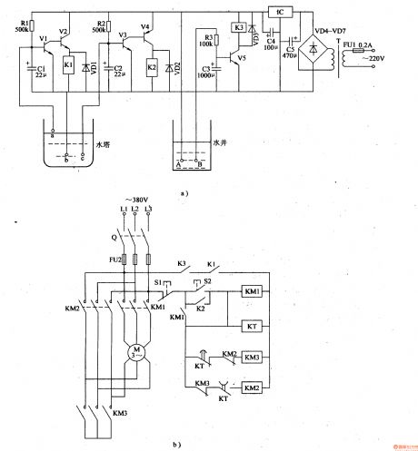
When the level is lower than b and c, V1-V4 are connected and K1 K2 are connected. If there is water, V5 is connected and M begins to work with a star-form. When KT finishes itstime delay, KM3 is released and M begins to work with a triangle-form.
When the level is higher than C, V3 V4 are disconnected and K2 is released. M is still working. When the level is higher, M stops working. When the level is lower than b,c, the circuit works as above and keep the level between a and c.
When there is lack ofwater, after V5 is disconnected and K3 is released, M stops working. (View)
View full Circuit Diagram | Comments | Reading(493)
Agricultural Automatic Water Feeder (3)
Published:2011/5/22 19:39:00 Author:Sue | Keyword: Agricultural, Automatic, Water Feeder
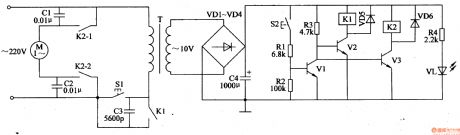
When the level is low, ac voltage of 220V will provide the circuit with 10V dc voltage. VL is illuminated.
When S2 is disconnected, V1 is disconnected. K2-1 and K2-2 are connected, and the motor begins to feed water.
When the level reaches the highest level, S2 is connected, and V1 is connected. K1 K2 are released. M stops working.
When the level is between the lowest and the highest, S2 is disconnected. When the level reaches the lowest, the circuit begins to work again, and M begins to feed water. (View)
View full Circuit Diagram | Comments | Reading(698)
Agricultural Automatic Water Feeder (1)
Published:2011/5/22 19:30:00 Author:Sue | Keyword: Agricultural, Automatic, Water Feeder
When Q is connected, AC voltage of 220V provides the circuit with 10V DC voltage.
When the level is lower than b, IC’s 2 pin and 6 pin have low level, and 3 pin outputs high level. M begins to feed water.
When the level reaches v, R2 will be short, and IC’s 2 pin and 6 pin have voltage higher than VCC/3,but lower than 2VCC/3. 3 pin outputs high level and M continues to feed water.
When the level reaches a, R1 is short, 3 pin has a low level, and M stops feeding water.
When the level is between a and b, M stops working, until the level is lower than b, M begins to work again.
It works like this and the level can be between a and b. (View)
View full Circuit Diagram | Comments | Reading(588)
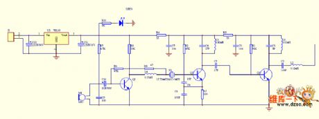
Intermediate Frequency Signal Generator Circuit Made of Ceramic Filter 3L465
Published:2011/5/19 10:09:00 Author:Joyce | Keyword: Intermediate Frequency, Signal Generator, Made of Ceramic Filter 3L465
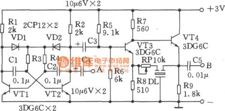
As shown in the figure is an intermediate frequency signal generator made of ceramic filter3L465.It is simple to handle and it will be esay to start oscillation.And the intermediate frequency signal produced by it is stable and have sound repeatability.It can output audio signal as well.Operating principle: VTl, VT2 and other related components constitute multivibrator with a frequency of about 400Hz.It can be used to regulate intermediate frequency signals and the audio signal can be output from point A. VT3, VT4 compose intermediate frequency signal generator, in which DL will select the frequency. Adjusting RP could change the oscillation intensity.Connecting a wire of dozens of cm long at point B can output the the modulated intermediate frequency signal.As for the multivibrator,as long as all the components are connected in the right way. oscillation will start as soon as swtiching on.
(View)
View full Circuit Diagram | Comments | Reading(788)
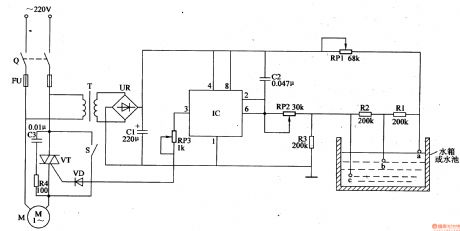
Electronic Pest Killing Lamp (2)
Published:2011/5/20 4:00:00 Author:Sue | Keyword: Electronic, Pest, Killing, Lamp
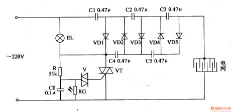
In the daytime, RG's resistance value is low, making CO circuit short. VT is disconnected because of lack of voltage, and the rectifying circuit doesn't work. When there is no light in the evening, RG has a large resistance value. R and CO begin to charge. When CO's voltage reaches a certain value, V and VT are connected. The rectifying circuit begins to work. The alternating current 220V voltage will generate 1450V high voltage, which will be put onto the electric net. When the pest touches the net, it will be killed by the high voltage. (View)
View full Circuit Diagram | Comments | Reading(731)
Electronic Bird Repeller (2)
Published:2011/5/20 5:13:00 Author:Sue | Keyword: Electronic, Bird, Repeller
When S is on, multivibrator generates signals. T generates 300V voltage and charges C2. When D3's voltage reaches 4.5V, D4's output has high level, making VD2 disconnected. Low frequency oscillator stops working. V2 is connected and YV is connected. The gong is knocked to make a sound.
When YV works, C2's voltage is used and C3's voltage is higher than 4.5V. D4's output has low level and VD2 is connected. V2 is disconnected, K and YV are released and C2 begins to charge. There will be anautomatic knock at the gang. (View)
View full Circuit Diagram | Comments | Reading(1364)
Electronic Bird Repeller (1)
Published:2011/5/20 5:06:00 Author:Sue | Keyword: Electronic, Bird, Repeller
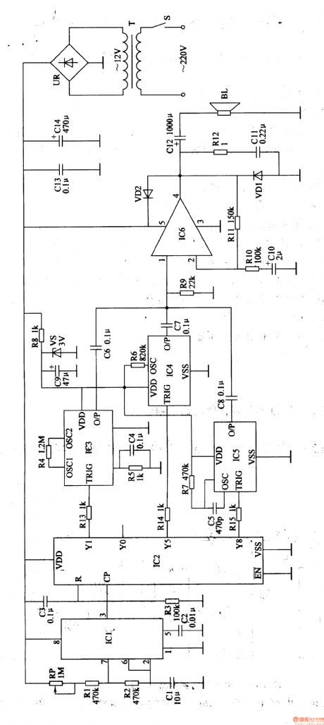
When S is on, 220V voltage will provide IC1,IC2,IC6,IC3,IC5 with working voltage.After the clockpulse generator begins to oscillate, IC2 will count the input pulse.
When the first pulse comes, Y1 outputs high level, and IC3 begins to work. O/P will output firecracker sound signals. BL will make a sound of firecracker.
When the 5th pulse comes, Y5 outputs high level, and IC4 begins towork. O/P will output sound signals and BL will make a sound of Di di, be careful .
When the 8th pulse comes, Y8 outputs high level, and IC5 begins to work. O/P will output bark signals and BL will make a barking sound.
When the 11th pulse comes, Y1 outputs high level again, BL makes a sound of firecracker. The circuit works in this order to drive birds away. (View)
View full Circuit Diagram | Comments | Reading(1864)
Water Level Indicator (5)
Published:2011/5/17 20:51:00 Author:Sue | Keyword: Water Level, Indacator
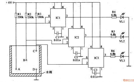
When there is no water, IC1-IC3 will output low level, VL1-VL3 are not illuminated.
When the level is lower than A, IC1’s inside circuit reverses, its 3 pin will output high level, illuminating VL1.
When the level reaches B, IC2’s 3 pin outputs high level, illuminating VL2.
When the level reaches C, IC3’s 3 pin outputs high level, illuminating VL3.
When the level is lower than C, IC3 reverses and 3 pin will have a low level, making VL3 go out.As the level becomes lower, VL2 and VL1 will go out one by one.. (View)
View full Circuit Diagram | Comments | Reading(1463)
Water Level Indicator (4)
Published:2011/5/17 20:46:00 Author:Sue | Keyword: Water Level, Indicator
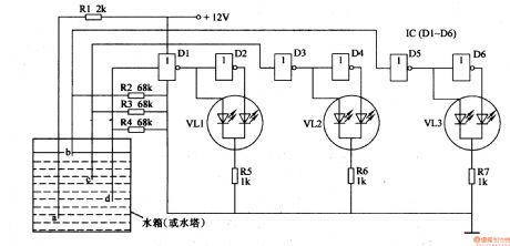
When water level reaches D, D1 will have a high level, and its output terminal has a low level, while D2’s output terminal has a high level. VL1 is green then. When the level is lower than D, D1’s input terminal will have a low level and D2’s output terminal will have a low level, making VL1 become red. Other circuits have the same working principle as this one.
When there is no water or water level is lower than d, VL1-VL3 are red.
When the level is the lowest, VL1 is green, VL2,VL3 are red.
When the level reaches 1/2, VL1,VL2 are green, VL3 is red.
When the level reaches B, VL1-VL3 are green. (View)
View full Circuit Diagram | Comments | Reading(2452)
| Pages:1841/2234 At 2018411842184318441845184618471848184918501851185218531854185518561857185818591860Under 20 |
Circuit Categories
power supply circuit
Amplifier Circuit
Basic Circuit
LED and Light Circuit
Sensor Circuit
Signal Processing
Electrical Equipment Circuit
Control Circuit
Remote Control Circuit
A/D-D/A Converter Circuit
Audio Circuit
Measuring and Test Circuit
Communication Circuit
Computer-Related Circuit
555 Circuit
Automotive Circuit
Repairing Circuit