
Circuit Diagram
Index 1860
RC Sine Wave Generator Circuit Composed of LM741CN
Published:2011/5/17 7:12:00 Author:Joyce | Keyword: RC, Sine Wave , Generator Composed of LM741CN
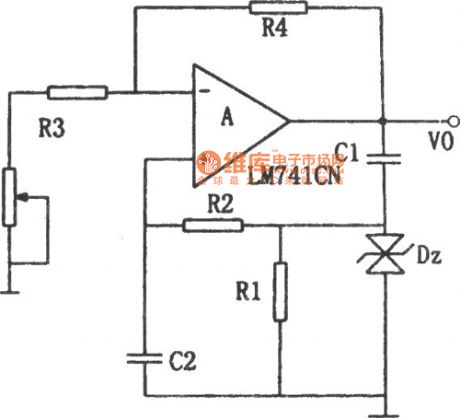
As shown in th (View)
View full Circuit Diagram | Comments | Reading(797)
555 light turn-off reminder circuit
Published:2011/5/16 6:17:00 Author:Christina | Keyword: light, turn-off, reminder
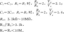
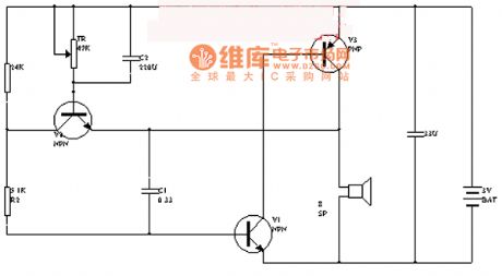
The 555 light turn-off reminder circuit is as shown. This circuit is composed of the monostable delay circuit, driver circuit, buzzer, LED.etc. And the monostable delay circuit's (composed of the 555 and R1, C3) output signal controls the rear circuit.
Power supply of the direction light relay gets through the diode and adds to the pin-8 of 555, this makes the capacitor C3 to be charged through R1. Pin-6's voltage level increases by charging, when pin-6's voltage level gets to 2/3VDD (about 1-minute delay), 555 overturns, the low level voltage of pin-3 makes the BG to conduct. The corresponding LED turns on, and the buzzer starts working, the sound and light signals remind the driver to turn off the light.
(View)
View full Circuit Diagram | Comments | Reading(1979)
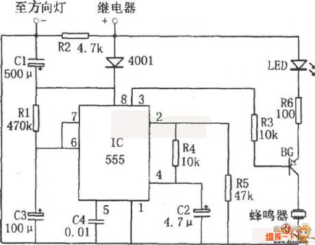
Wideband Video Amplifier Circuit with 50Ω Input/Output Impedance
Published:2011/5/17 6:28:00 Author:Joyce | Keyword: Wideband Video, Amplifier, with 50Ω Input/Output Impedance
 (View)
View full Circuit Diagram | Comments | Reading(747)
Utility Voice Control Electronic Doorbell Circuit
Published:2011/5/17 6:31:00 Author:Joyce | Keyword: Utility , Voice Control , Electronic , Doorbell
View full Circuit Diagram | Comments | Reading(719)
Inverter (2)
Published:2011/5/16 3:34:00 Author:Sue | Keyword: Inverter (2)
Working Principle:
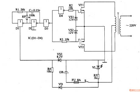
When power switch S is connected, low frequency oscillator begins to work and generates 50Hz oscillator signals. After the signal is buffered and reshaped by NOT gate D3, it will be sent to VF2's grid electrode through R3, and the other circuit will be sent to VF1's grid electrode after it is backward processed by NOT gate D4. So VF1 will work during the oscillator signal's positive half period while VF2 will work during the signal's negative half period. Finally after the signal is push-pull amplified, it will generate a alternating voltage of 220V at the two terminal of T's secondary winding. (View)
View full Circuit Diagram | Comments | Reading(1504)
Infrared emission circuit with the printing quartz crystal oscillator
Published:2011/5/16 8:04:00 Author:Christina | Keyword: Infrared emission, printing quartz, crystal oscillator
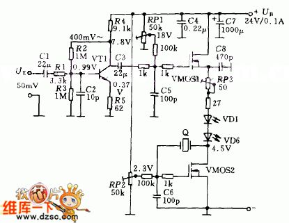
The Infrared emission circuit with the printing quartz crystal oscillator is as shown. The oscillator is composed of the crystal Q, the VMOS transistors mosfet and the external components. The low frequency modulation signal UE adds the the amplifier VT1 through the capacitance C1. The modulated signal with the carrier wave is amplified by the VMOS1 mosfet and is output by the infrared diodes VD1 ~ VD6.
(View)
View full Circuit Diagram | Comments | Reading(1177)
fast inverting amplifier with high input impedance circuit
Published:2011/5/15 2:33:00 Author:John | Keyword: fast inverting amplifier
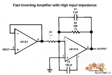
Fast inverting amplifier with high input impedance circuit is shown below.
(View)
View full Circuit Diagram | Comments | Reading(1216)
Inner Circuit Pane and Pin Function Circuitof M50462AP IC
Published:2011/5/16 8:30:00 Author:Michel | Keyword: Inner Circuit Pane, Pin Function, IC
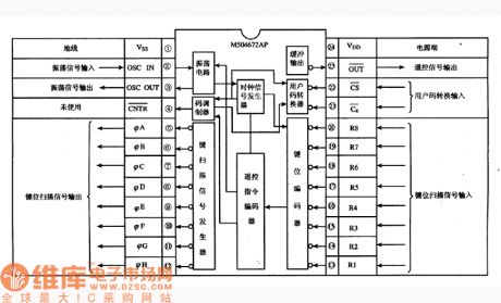
Features and Functions
M50462AP IC generates remote control coding impulse,namely remote control command and outputs infrared remote control singal,which is used to remote control.This IC has three functions.
Firstly,it generates timing signal and remote carrier signal oscillator.Secondly,it generates 8 key sweep gate generators which appear at different time.Thirdly,it changes key codes(code value change) into teleswitch command encoder of remote command function code.
Pin Function and Data
M50462AP IC's plastic package adopts 24 pins dual inline type and the inner circuit pane and all pins' functions are showed as above. (View)
View full Circuit Diagram | Comments | Reading(835)
Typical Application Circuit of M50462AP IC
Published:2011/5/16 8:17:00 Author:Michel | Keyword: IC, Application Circuit
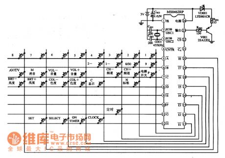

Typical Application Circuit
Typical application circuit of remote control emitter composed of M50462AP IC is showed as above.
Note:(23)pin of M50462AP IC outputs carrier signal and the signal amplifies via V001 which gives VD001 an impulse to launch infrared light signal.
Picture:Typical Application Circuit of M50462AP IC (View)
View full Circuit Diagram | Comments | Reading(825)
Music type refrigerator door closing reminder circuit
Published:2011/5/16 8:40:00 Author:Christina | Keyword: Music type, refrigerator, door closing, reminder
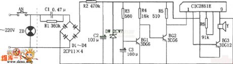
The Music type refrigerator door closing reminder circuit is as shown. This circuit is composed of the step-down rectifier voltage-stabilizing circuit, the delay circuit, the music IC CIC2851E, the speaker.etc. The step-down rectifier voltage-stabilizing circuit supplies the 3V DC voltage to the whole circuit.
When you open the door of fridge, switch AN connects. and the capacitor C3 is charged through R3, BG1's base potential rises, after about 20 minutes delay, C3's voltage makes BG1 conduction, and makes the BG2 cut-off, and this voltage triggers the CIC2851E to work, the output music signal is amplified by BG3 and drives the speaker Y to send out the music of ling er xiang ding dang.... to remind the master to close the door quickly.
(View)
View full Circuit Diagram | Comments | Reading(1086)
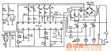
Multifunction Charger One
Published:2011/5/17 3:34:00 Author:Michel | Keyword: Multifunction Charger, One
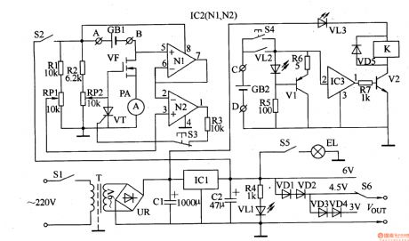
The Multifunctions Charger introduced in the example can charge in constant-current way,charge in regulating current way and the maximum current is 500nA.It can carry out standard and fast charge and stop charging automatically when the battery is fully charged.This charger can charge two pieces of aa(aaa)nickel-spread battery,nickel-hydrogen batteries,alkaline cells at a time.It also can be used as the constant-voltage power supply of miniature radios and videocorders.Circuit's Work PrincipleThis multi-functions charger is composed of power supply circuit,lamp circuit and discharge circuit and it's showed as the picture 5-63. (View)
View full Circuit Diagram | Comments | Reading(613)
RC reset circuit increases the discharge loop
Published:2011/5/16 7:39:00 Author:Christina | Keyword: discharge loop, RC reset circuit
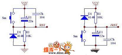
You can solve the system instability which is caused by the power glitch by using the comparison circuit, and the power slow dropping can be reliably reset. Figure 4 is the example: when VCCx(R1/(R1+R2))=0.7V, Q1 closes to reset the system Q1. The amplification of Q1 also improves the load characteristics of the circuit, but the transition threshold voltage Vt is affected by the Vcc, this is the most prominentest weak point of this circuit, so you can use the zener diode to make the Vt will not affected by the Vcc. Figure 5: when Vcc is lower than Vt(Vz+0.7V), the circuit reset the system.
Figure: RC reset circuit increases the discharge loop (View)
View full Circuit Diagram | Comments | Reading(3811)
Lithium Dry Battery Charger Five
Published:2011/5/16 23:02:00 Author:Michel | Keyword: Lithium Dry battery Charger, Five
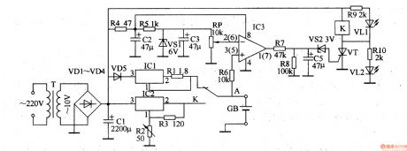
The lithium battery charger introuduced in the example can charge 6V-plated ion battery in constant-current way and change into constant-voltage chagre mode when the battery reaches 4·1V.
Work Principle of the Circuit
This lithium battery charger circuit is composed of power supply constant voltage circuit,oscillator,voltage detection control circuit,constant-current charge circuit and constant-voltage charge circuit and it's showed as the picture 5-77.
The power supply constant-voltage circuit is composed of power supply transformer,T,commutation diode,VDl-VD4,filter capacitor,CI and C2 and three-terminal voltage control IC1. (View)
View full Circuit Diagram | Comments | Reading(2549)
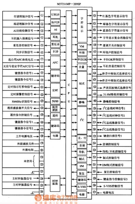
Inner Circuit Block Plan and Signal Flow Direction Circuit of M3727 and MP-209SP
Published:2011/5/16 21:37:00 Author:Michel | Keyword: Inner Circuit Block Plan, Signal Flow Direction Circuit
(View)
View full Circuit Diagram | Comments | Reading(748)
HA1371-BTL-the Integrated Circuit of Audio Amplifier
Published:2011/5/13 7:40:00 Author:Borg
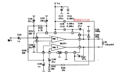
HA1371 is an integrated circuit of audio amplifier produced by Hitachi Corp.,Japan, which is used in high-power radios and computer stereos as amplifier circuits.1.the internal circuit of HA1371HA1371 is a BTL circuit which characterizes with slight impulse noise of turning on/off power, big output power and wide voltage range. It is in 12-lead dual-line package, whose internal circuit and typical application circuit are as shown in Figure 1-1, and pin functions and data are listed in Table 1-1.
(View)
View full Circuit Diagram | Comments | Reading(2026)
Pin Function Circuit of M50453-012P IC
Published:2011/5/16 9:10:00 Author:Michel | Keyword: Pin Function, Circuit, IC
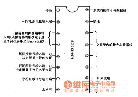
Pin Function Circuit of M50453一012P IC
M50453一012P IC contains symbol signal generating circuit,line and field location signal processing circuit,system command and data decoder processing circuit.
Pin Function and Data
M50453一012P IC adopts 16 pins dual inline type packaging and its pins' functions are showed as above.
Picture:Pins' Functions ofM50453-012P IC
(View)
View full Circuit Diagram | Comments | Reading(1828)
Pin Function Circuit of M50450-023P IC
Published:2011/5/16 9:38:00 Author:Michel | Keyword: Pin Function Circuit, IC
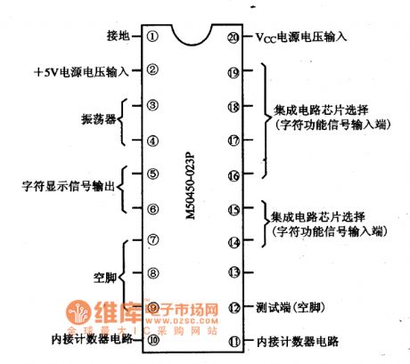
Functions and Features
M50450一023P IC containsclockoscillator,character signal generating circuit and relative control circuit.
Pins' Functions and Data
M50450-023P IC adopts 20 pins dual inline type packaging and its pins' functions are showed as above.
Picture:Pins' Functions of M50450一023PIC (View)
View full Circuit Diagram | Comments | Reading(1634)
Typical Application Circuit of M50436-683SP IC
Published:2011/5/16 9:59:00 Author:Michel | Keyword: Typical Application Circuit, IC
(View)
View full Circuit Diagram | Comments | Reading(869)
Pin Function Circuit of M50143-006P IC
Published:2011/5/16 10:11:00 Author:Michel | Keyword: Pin Function Circuit, IC
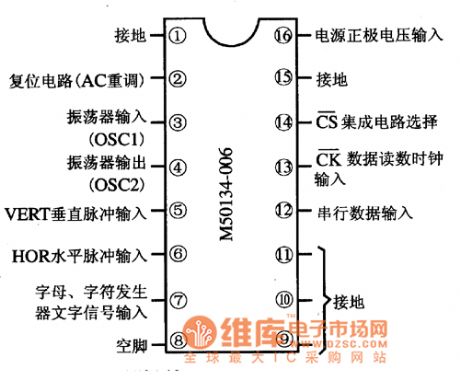
Functions and Features
There are M50143-006P IC's clock oscillator circuit,serial data interface circuit,line and filed impulse generating circuit and character signal generating circuit etc.
Pins' Functions and Data
M50143-006P IC adopts 16 pins dual inline type packaging and its pins' functions are showed as above.
Picture:Pins' Functions of M50143-006P
(View)
View full Circuit Diagram | Comments | Reading(983)
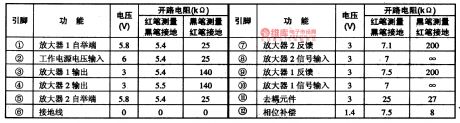
Hotbox Overheating Components Circuit
Published:2011/5/17 3:54:00 Author:Sharon | Keyword: Hotbox, overheating components
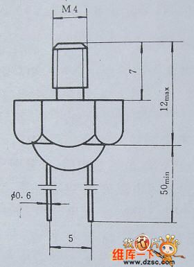
Figure 1 Typical dimensions of temperature probe
PTC thermistor RT is a key component in hotbox overheating protection circuit, and its room temperature resistance is ≤ 500Ω.Its typical dimension is shown in Figure 2.10.2. The shell is made from brass screws with PTC thermistor sealed inside, and it's ensured a good heat conduction and electrical insulation with the shell.
(View)
View full Circuit Diagram | Comments | Reading(864)
| Pages:1860/2234 At 2018411842184318441845184618471848184918501851185218531854185518561857185818591860Under 20 |
Circuit Categories
power supply circuit
Amplifier Circuit
Basic Circuit
LED and Light Circuit
Sensor Circuit
Signal Processing
Electrical Equipment Circuit
Control Circuit
Remote Control Circuit
A/D-D/A Converter Circuit
Audio Circuit
Measuring and Test Circuit
Communication Circuit
Computer-Related Circuit
555 Circuit
Automotive Circuit
Repairing Circuit