
Circuit Diagram
Index 1842
Agricultural Automatic Water Tap (2)
Published:2011/5/19 3:25:00 Author:Sue | Keyword: Agricultural, Automatic, Water Tap
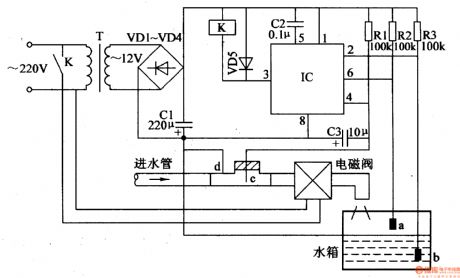
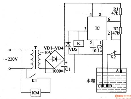
When the water level is lower than v, IC's 3pin will output high level, making K work, and therewill bewater pouring into the water tank. When the level is higher than a, IC's 3 pin will have a low level, and K, magnetic valve will stop working. The water supply will be stopped.
When there is no water in the inlet pipe, IC's 4 pin will have a low level, and IC's 3 pin will output low level. Kand the magnetic valve don't work.
To avoid gas in the water pipe, C3 will be set as time delay capacitor. (View)
View full Circuit Diagram | Comments | Reading(2061)
Agricultural Automatic Water Tap (1)
Published:2011/5/19 3:18:00 Author:Sue | Keyword: Agricultural, Automatic, Water Tap

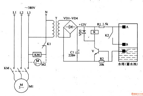
When the water level doesn’t reach the certain level, the circuit doesn’t work. When there is water in inlet pipe, VL1,VL2’s negative poles will have low level, which will make V1 disconnected and V2 connected. K is connected and YV begins to work, adding water into the water tank.. Then VL2 is illuminated. When the water reaches a certain level, V1 is connected, and V2 is disconnected. K is released, and YV is disconnected. Then water supply is stopped. At the same time, VL1 is illuminated. If there is no water in the inlet pipe, VL2,VL1’s negative poles will have high level, making V1,V2 disconnected, and K, YV don’t work. (View)
View full Circuit Diagram | Comments | Reading(2367)
Agricultural Automatic Water Feeder (15)
Published:2011/5/22 20:41:00 Author:Sue | Keyword: Agricultural, Automatic, Water Feeder
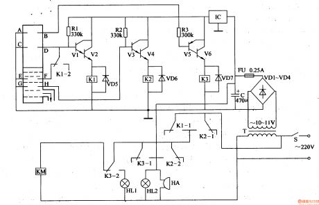
When the level is lower than E,F, V1 and V2 are connected and K1 is connected. KM is connected and M begins to feed water. When the level is higher than C,D, V1 and V2 are disconnected and K is relealsed. KM is released and M stops working. When the level is lower than E,F, M begins to work again.
If C,D or D,F stop working, the protection system will begin to work. When the level is higher than C,D, M is still working. When the level reaches the highest, V5,V6 are connected and KM is released. M stops working. At the same time, the HL1 HL2 will be illuminated. HA will make an alarm sound.Ifthe level is lower than E,F, M is still not working, V3,V4 will be connected and KM is connected. M will begin to feed water. HL2 is illuminated and HA makes an alarm sound. (View)
View full Circuit Diagram | Comments | Reading(656)
Agricultural Automatic Water Feeder (14)
Published:2011/5/22 20:35:00 Author:Sue | Keyword: Agricultural Automatic Water Feeder
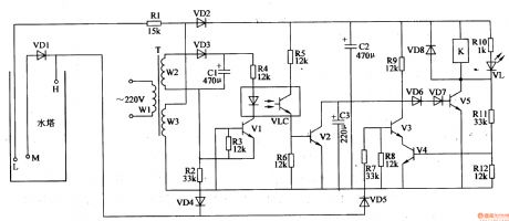
When there is no water, VD4 VD4 V1-V4,VLC are disconnected. VD6 VD7 and V5 are connected and M begins to work and feed water. VL is illuminated.
When the level reaches M, VD5 is connected. V3 has high level. V4,V3 are disconnected and M keeps on working.
When the level reaches H, V5 is disconnected and VL goes out. K is released and M stops working.
When the level is lower than H, VD4,V1,VLC and V2 are disconnected and V4 is connected. V5 is disconnected.
When the level is lower than M, V5 is connected and K is connected. VL is illuminated and M begins to feed water again. (View)
View full Circuit Diagram | Comments | Reading(590)
Agricultural Automatic Water Feeder (13)
Published:2011/5/22 20:30:00 Author:Sue | Keyword: Agricultural, Automatic, Water Feeder
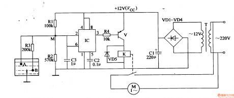
When the level is lower than B, IC's 2 pin has high level and IC's inside trigger reverses. 3 pin outputs low level. V is connected and K is connected. M begins to work and feed water.
When the level reaches b, IC's 2pin has a voltage of Vcc/2, the trigger remain what it is and M keeps on working.
When the level reaches A, IC's 2 pin has low level and 3 pin output high level, V is disconnected and K is released. M stops working. (View)
View full Circuit Diagram | Comments | Reading(657)
Agricultural Automatic Water Feeder (12)
Published:2011/5/22 20:26:00 Author:Sue | Keyword: Agricultural, Automatic, Water Feeder
When the level is lower than b, IC's 2 pin is high level and 3 pin outputs low level. K is connected and K1 is connected. K2 is disconnected and KM is connected. M begins to feed water.
When the level reaches A, IC's 2 pin becomes low level and 3 pin outputs high level. K is released and K1 is disconnected. K2 is connected and KM is disconnected. M stops working.
When the level is lower than b, IC's 2 pin becomes high level and 3 pin output low level. K and KM are connected and M begins to feed water again. (View)
View full Circuit Diagram | Comments | Reading(657)
Agricultural Automatic Water Feeder (11)
Published:2011/5/22 20:23:00 Author:Sue | Keyword: Agricultural, Automatic, Water Feeder
When the level is lower than b, V is disconnected and K doesn't work. Its K2 is disconnected and K1 is connected. M begins to feed water.
When the level reaches A, +12V voltage is put on V, making V connected. K begins to work. Its K is disconnected and K2 is connected. M stops working.
When the level is lower than B, V is disconntected and K is released. K2 is disconnected and K1 is connected. KM is connected and M begins to work again.
The circuit works like this and feed water automatically. (View)
View full Circuit Diagram | Comments | Reading(605)
Electronic Pest Killing Lamp (8)
Published:2011/5/20 4:53:00 Author:Sue | Keyword: Electronic, Pest, Killing, Lamp
Working Principle:
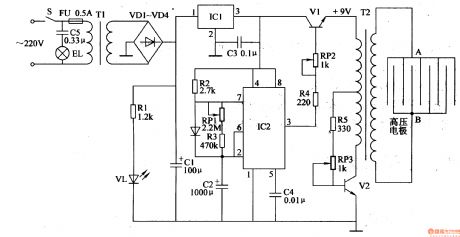
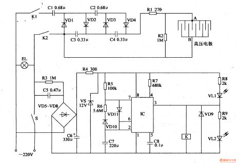
As seen in the figure 4-187, the circuit consists of power circuit, pulse oscillator and high voltage generator.
The power circuit consists of S,FU,TI,VD1-VD4,C1,C3,IC1,R1 and VL.
The pulse oscillator consists of IC1,R2,R3,RP1 and C2.
The high voltage generator consists of V1,V2,RP2,RP3,R4,R5,T2.
EL is the trap lamp and C5 is reduction voltage capacitor.
When S is on, 220V voltage will illuminate EL. The other circuit will provide the pulse oscilator and high voltage generator with +12V working power after reduction, rectification, filtering by T1,VD1-VD4,C1. The voltage which is rectified will illuminate VLA. (View)
View full Circuit Diagram | Comments | Reading(2965)
Electronic Pest Killing Lamp (7)
Published:2011/5/20 4:44:00 Author:Sue | Keyword: Electronic, Pest, Killing, Lamp
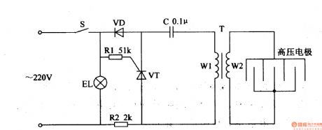
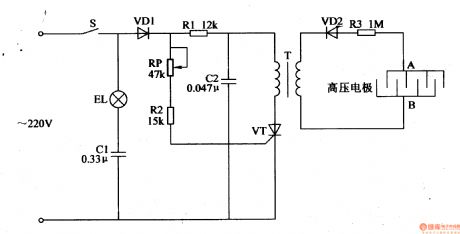
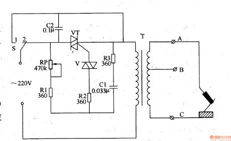
As seen in the figure 4-186, the circuit consists of power switch S, trap light EL, diode VD, thyristor VT, resistor R1 R2, capacitor C, pulse high voltage transformer T and high voltage electrode.
When S is connected, 220V voltage will illuminate EL. The other circuit will provide the pulse oscillator circuit with working voltage. VT will be connected intermittently. T will generate 10kV pulse high voltage which will kill the pest that touches the electric net. (View)
View full Circuit Diagram | Comments | Reading(1035)
Electronic Pest Killing Lamp (6)
Published:2011/5/20 4:36:00 Author:Sue | Keyword: Electronic, Pest, Killing, Lamp
When the power is on, alternating current 220V voltage will illuminate EL after the voltage is reduced by C1. The other circuit will provide VT's positive pole with working voltage, making VT work in the positive half period and stop working in the negative half period. T will generate pulse high voltage which will be put on the high voltage electric net after the voltage is rectified and reduced by VD2 and R3. When the pest touches the net, it will be killed by the high voltage. (View)
View full Circuit Diagram | Comments | Reading(726)
Electronic Pest Killing Lamp (5)
Published:2011/5/20 4:28:00 Author:Sue | Keyword: Electronic, Pest, Killing, Lamp
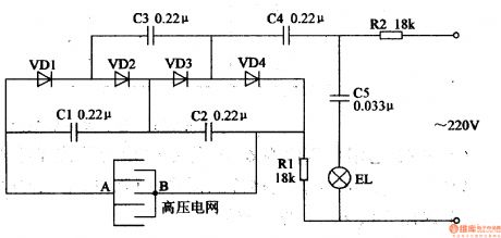
The circuit consists of resistor R2, capacitor C5 and trap lamp EL.
The high voltage generator consists of resistor R1, capacitor C1-C4, diode VD1-VD4 and high voltage electric net.
When the 220V voltage is put on EL, it will make EL illuminated. The other circuit will generate direct current high voltage which will be put on A,B. When the pest touches EL, it will be killed by the high voltage. (View)
View full Circuit Diagram | Comments | Reading(1224)
Electronic Pest Killing Lamp (4)
Published:2011/5/20 4:24:00 Author:Sue | Keyword: Electronic, Pest, Killing, Lamp
220V voltage will provide the circuit with +12V working power.
When IC begins to oscillate, its 3 pin will output low frequency pulse signal. When IC's 3 pin outputs high level, K is connected, V is illuminated and VL1 goes out.After 220V voltage is rectified, it will generate 1000V high voltage which will be put onto the high voltage electrode. When IC's 3 pin outputs low level, K is released, VL2 goes out, VL1 is illuminated. K's K1 and K2 are connected, and the high voltage generator stops working. (View)
View full Circuit Diagram | Comments | Reading(1227)
Electronic Pest Killing Lamp (3)
Published:2011/5/20 4:11:00 Author:Sue | Keyword: Electronic, Pest, Killing, Lamp
Working Principle:
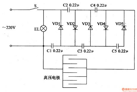
As seen in the 4-182, the citcuit consists of powering switch S, trap light EL, high voltage electrode, capacitor C1-C5 and diode VD1-VD5.
In the circuit, C1-C5 and VD1-VD5 make up a 5 times voltage rectification circuit.
When S is connected, EL is illuminated. 220V voltage will generate 1400V pulse voltage,which will be put onto the high voltage electrode. In the evening , when the pest touch the net, it will be killed by the high voltage.
(View)
View full Circuit Diagram | Comments | Reading(771)
Electronic Pest Killing Lamp (1)
Published:2011/5/20 3:53:00 Author:Sue | Keyword: Electronic, Pest, Killing, Lamp

In the daytime, IC's 6 pin has a high level, 3's pin has a low level and VF1 is disconnected. The whole circuit doesn't work. In the evening, IC1's 2 pin has a low level, 3 pin has a high level, and VF1 is connected. The circuit begins to work. When the multivibrator begins to work, IC2's 3 pin outputs oscillator signals. The signal will generate alternating current 220V voltage, illuminating EL. Another circuit will generate high voltage,which will be sent to the electronic net. (View)
View full Circuit Diagram | Comments | Reading(672)
Electronic Pest Repeller (1)
Published:2011/5/19 3:02:00 Author:Sue | Keyword: Electronic, Pest Repeller
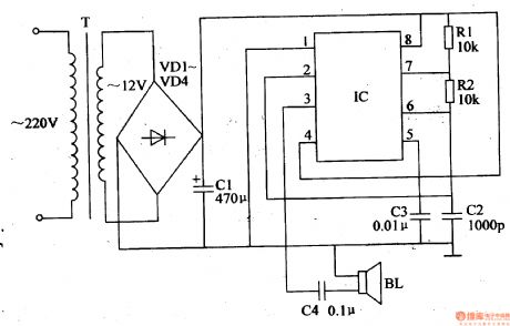
As seen in figure 4-178, the electronic pest repeller circuit consists of power circuit and multivibrator circuit.
When the power is on, an ac voltage of 220V will generate 12V direct voltage after the reduction, rectification and filtering by T, VD1-VD4 and C1. The 12V voltage will be sent to IC.
After the multivibrator begins to work, IC's 3 pin will output square form wave with a frequency of 48kHz, which will be transformed to ultrasonic wave by BL. The ultrasonic wavewill beemitted and can repel the pests.
When R1,R2's resistance value or C2's capacity are changed, the working frequency of the multivibrator can be changed.
(View)
View full Circuit Diagram | Comments | Reading(1980)
Electronic Bird Repeller (5)
Published:2011/5/20 5:33:00 Author:Sue | Keyword: Electronic, Bird, Repeller
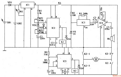
In the daytime, IC1's inside switch is on and A will oscillate, outputting low frequency oscillator signals. When IC2's 3 pin outputs high level, K1 is connected. IC2's 2 pin will output 6 V voltage which will provide driving circuit with working voltage. The other circuit will provide IC3 with 3V working voltage. When IC2's 3 pin outputs low level, IC3-IC5 stops working.
When IC3 begins to work, O/P outputs signals, and BL makes a sound of fire cracker.
In the evening, VD1 is disconnected and the circuit doesn't work. (View)
View full Circuit Diagram | Comments | Reading(4114)
Electronic Bird Repeller (4)
Published:2011/5/20 5:27:00 Author:Sue | Keyword: Electronic, Bird, Repeller
When S is on, the square form wave generator begins to work and outputs square form pulse signal with an adjustable duty ratio. When the pulse delays upgoing, VF1 is connected. The audio signals it generates will drive BL to make a DU sound. When the pulse delays downgoing, VF1 is disconnected and the multivibrator stops working. In this circumstances, the multivibrator and the audio driving circuit works intermittently under the control of the signals and power circuit. (View)
View full Circuit Diagram | Comments | Reading(2546)
Electronic Bird Repeller (3)
Published:2011/5/20 5:22:00 Author:Sue | Keyword: Electronic, Bird, Repeller
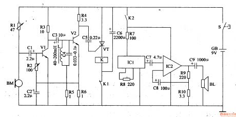
When there is bird, VT is disconnected,Kdoesn't work and BL makes no sound.
When there is bird, BM will transform the bird singing into electric signal, which will be sent to VT and make VT connected after the signal is amplified. K is connected and BL makes a sound of firecracker. When K is connected, C6 discharges until K is released. Then K2 is disconnected, sound circuit and audio amplifier will stop working. BL stops making a sound. (View)
View full Circuit Diagram | Comments | Reading(661)
Eyesight Preserver (the 1st)
Published:2011/5/22 6:56:00 Author:Felicity | Keyword: Eyesight Preserver (the 1st)
Work of the circuit
The circuit consists of light examining circuit, LED shining circuit and voice prompting circuit (It is showed in picture 9-59.).
Turn on power switch S and battery GB supplies 3V voltage to the whole circuit. When the environment light is strong enough the voltage of VD is not so high. Here VL does not shine and HA makes no sound. When the environment light is dim the voltage of VD is high. Here VL shines and HA makes the sound “tick tick”. (View)
View full Circuit Diagram | Comments | Reading(599)
Smoking Warning Indicator (2)
Published:2011/5/13 6:09:00 Author:Sue | Keyword: Smoking, Warning, Indicator
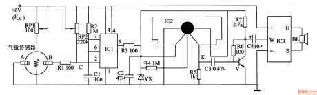
When gas sensor detects no smoke, the resistance value between A and B is large, and IC1's 2 pin has high level, 3 pin outputs low level. Then the sound generator circuit and audio power amplifying circuit don't work, so BL makes no sound.
When gas sensor detects smoke, the resistance value between A and B becomes small, lowering IC1's 2 pin's voltage. When the voltage is reduced under VCC/3, the monostable trigger reverses, making IC1's 3 pin's voltage change from low level to high level. The high level can generate 4.2V direct current voltage, which will be sent to audio integrated circuit IC2. IC2 begins to work and outputs sound signal, which can promote BL to make a warning sound of No Smoking please! . (View)
View full Circuit Diagram | Comments | Reading(1165)
| Pages:1842/2234 At 2018411842184318441845184618471848184918501851185218531854185518561857185818591860Under 20 |
Circuit Categories
power supply circuit
Amplifier Circuit
Basic Circuit
LED and Light Circuit
Sensor Circuit
Signal Processing
Electrical Equipment Circuit
Control Circuit
Remote Control Circuit
A/D-D/A Converter Circuit
Audio Circuit
Measuring and Test Circuit
Communication Circuit
Computer-Related Circuit
555 Circuit
Automotive Circuit
Repairing Circuit