
Circuit Diagram
Index 1852
Op amp differential mode voltage breakdown input stage protection measure circuit 1
Published:2011/5/17 2:07:00 Author:Rebekka | Keyword: Op amp, differential mode v, oltage breakdown , input stage, protection measure
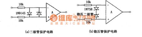
The over-voltage protection circuit that does not add an internal protection measures is shown as figure (a), (b). Figure (a) is the diode protection circuit. Figure (b) is regulator protection circuit. In the specific application, you only need to select one of them. The resistance shown in the figure is limiting current clamp resistance. Its value is up to 10kΩ and the offset voltage will not decrease. In practical applications. The input end of resistance may be the signal input. Usually, to improve the DC accuracy, you can access the same resistance to each input end. In some cases, you only need to input resistor and feedback resistor to achieve the limit of clamping diode current. It can save one or two resistors. (View)
View full Circuit Diagram | Comments | Reading(1053)
Multifunction Charger Seven
Published:2011/5/18 10:39:00 Author:Michel | Keyword: Multifunction Charger Seven
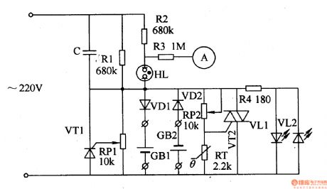
The multifunction charger introduced in the example has the functions of constant current pulse charging,voltage limiting protection,constant and excess temperature protection.It can charge one nickel-spread and nickel-hydrogen battery.
Circuit's Work Principle
This Multifunction charger consists of step-down capacitor,C,thyristor,VT1 and VT2,resistor,R1-R4,diode,VD1,VD2,potentiometer,RP1 and RP2,heat-variable resistor,RT and LED VD1 and VD2 and it's showed as the picture 5-69.The alternating voltage(220V) charges batteries GB1 and GB2 via VD1 and VD2 when it reduces voltage through C. (View)
View full Circuit Diagram | Comments | Reading(999)
Multifunction Charger Six
Published:2011/5/18 10:32:00 Author:Michel | Keyword: Multifunction Charger Six
The Multifunction charger introduced in the example can charge nickel-hydrogen batteries and alkaline cells with simple circuit and material.It can charge four pieces of battries at the most one time and stop charging automatically when batteries are fully charged.Circuit's Work PrincipleThis multifunction charger consists of mains transformer,T, rectifier bridge,UR, three-terminal adjustable IC regulator,IC,transistor,V1-V4,LED,VL1-VL4,resistor,R1-R9 and potentiometer,RP and it's showed as the picture 5-68.The alternating voltage(220v) changes to 6v volts d.c.when it passes T and UR.The voltage is added to VLl-VL4's anode as charging voltage and used as charging reference voltage when it passes IC. (View)
View full Circuit Diagram | Comments | Reading(618)
Multifunction Charger Eight
Published:2011/5/18 10:43:00 Author:Michel | Keyword: Multifunction Charger Eight
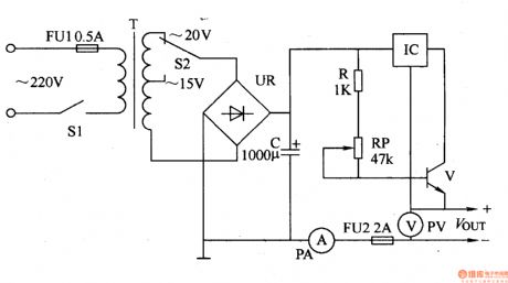
Simple circuit and convenience are features of the multifunction charger introduced in the example.It can charge 1.2-12V nickel-spread nickel-hydrogen and lead-acid batteries and also be used as working power supply of household appliances such as walkman.
Circuit's Work Principle
This multifunction charger consists of voltage change circuit and voltage regulation circuit and it is showed as the picture 5-70.The voltage change circuit is composed of mains switch,S1,voltage-selected switch,S2,fuse plug,FU1,mains transformer,T and rectifier bridge UR and filter capacitor,C.
(View)
View full Circuit Diagram | Comments | Reading(656)
Multifunction Charger Five
Published:2011/5/18 10:28:00 Author:Michel | Keyword: Multifunction Charger Five
Besides nickel-pick batteries,nickel-hydrogen cells and lithium-ion batteries,the Multifunction charger introduced in the example can also chagres plain alkaline cells and it chagres two to six pieces of batteries at a time.
Ciruit's Work Principle
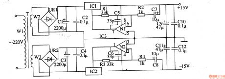
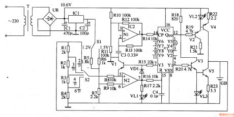
This multifunction charger consists of voltage regulator circuit,charging circuit and discharge circuit,battery selection or voltage detection circuit and sequential control circuit and is showed as the picture 5-67,The voltage regulator circuit is composed of mains transformer,T,rectifier bridge UR circuit,filter capacitor,C1 and C2 and three-terminal voltage regulation IC,IC1. (View)
View full Circuit Diagram | Comments | Reading(1396)
BA6286N-the bilateral control integrated circuit of motor drive
Published:2011/5/17 20:47:00 Author:Borg | Keyword: bilateral control, integrated circuit
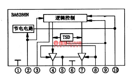
BA6286N is a bilateral control integrated circuit of motor drive produced by Toyo Corp., which is used in CD ,VCD,SVCDand VCD players as motor drivers.1.the internal circuitBA6286N contains logic control circuit and energy-saving circuit, which can provide drive current of 100Am, and its internal circuit is as shown in Figure 1.
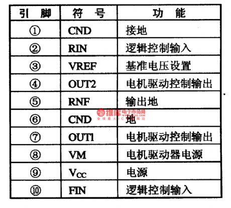
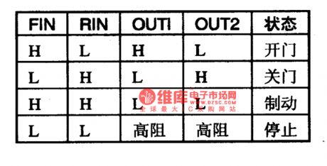
2.pin functionsBA6287N is in 10-lead single line package, whose pin functions are listed in Table 1.Notes: the logic control values of BA6287N are listed in Table 2, by which we can judge if IC is malfunctioning.
(View)
View full Circuit Diagram | Comments | Reading(882)
GD9915-an integrated microcomputer circuit of communication single door
Published:2011/5/13 6:27:00 Author:Borg | Keyword: microcomputer, communication single door
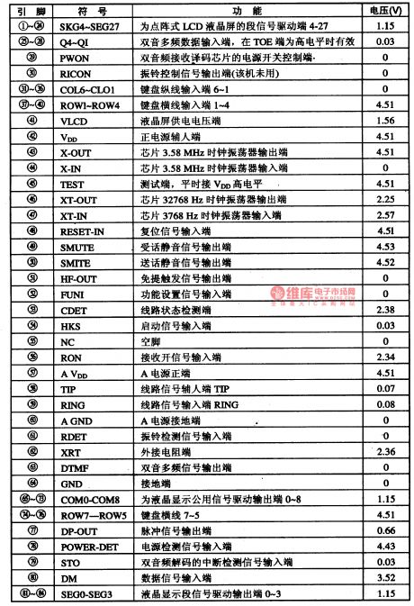
GD9915 is an integrated microcomputer circuit of communication single door, which is used in caller display phones.Function featuresGD9915 is a four bit microprocessor, which can not only control the reception, handling and displaying data of call FSK and DTMF, but also has other functions like pulse/two-tone coupling dialing and so on. (1) it contains FSK decipherers which are conforming to BELL202 and ITU-TV23. (2) it contains LCD drive and control circuits, which can directly drive the LCD display.
(View)
View full Circuit Diagram | Comments | Reading(546)
BA3503F-the integrated reproducing circuit of single door stereo
Published:2011/5/18 23:50:00 Author:Borg | Keyword: integrated reproducing circuit, single door
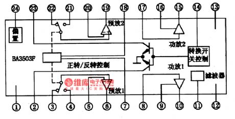
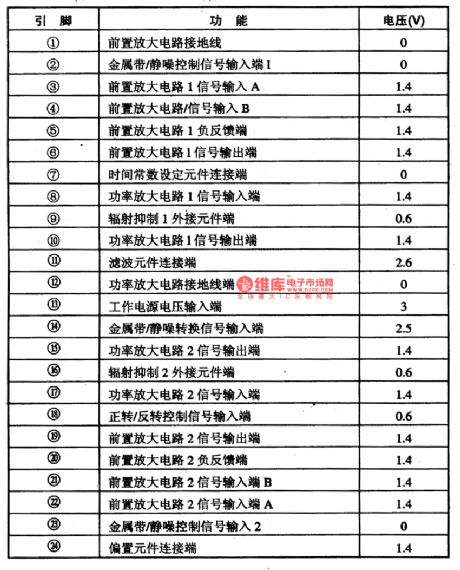
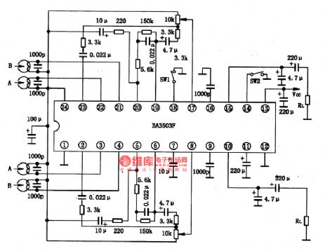
BA3503F is an integrated reproducing circuit of single door stereo produced by Toyo Power Tool Corp., Japan, which is an integrated preamplifier of 4-input auto-switching dual-channel. It is fit for small-sized low-voltage auto-reversing radios. 1.the internal circuit and pin functions of BA3503F BA3503F contains 2-channel preamplifier and separated 2-channel power amplifier circuit, whose internal circuit is shown in Figure 1. It is in flat 24-lead dual line package, and its pin functions and data are listed in Table 1.
(View)
View full Circuit Diagram | Comments | Reading(962)
BA3502F-the integrated reproducing circuit of single door stereo
Published:2011/5/18 22:17:00 Author:Borg | Keyword: integrated reproducing circuit, single door
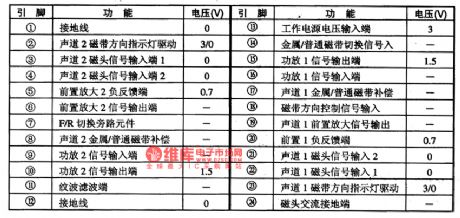
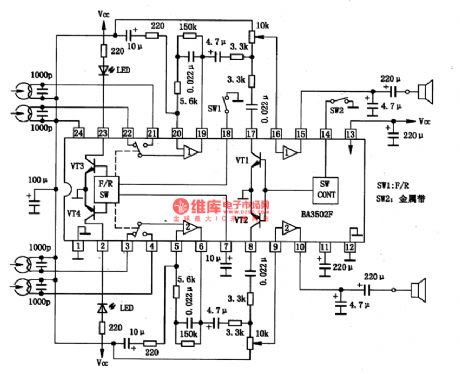
BA3502F is an integrated reproducing circuit of single door stereo produced by Toyo Power Tool Corp., Japan, which is used in ultra-small and ultra-slim radios.1.the internal circuit and pin functions of BA3502FThe internal circuit of BA3502F consists two lines of identical preamplifier circuits, power amplifier circuit, tape running direction switching and displaying circuits and tape type selecting circuits, which is a integrated reproducing circuit of multiple functions.The internal circuit and typical application circuit of BA3502F are listed in Figure 1.
(View)
View full Circuit Diagram | Comments | Reading(805)
The circuit of fault repairing on the unlighted engine service indicators of Daewoo-ESPERO
Published:2011/5/19 0:02:00 Author:Borg | Keyword: fault repairing, engine service indicators, Daewoo-ESPERO
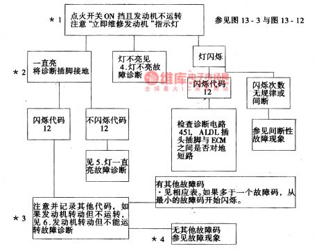
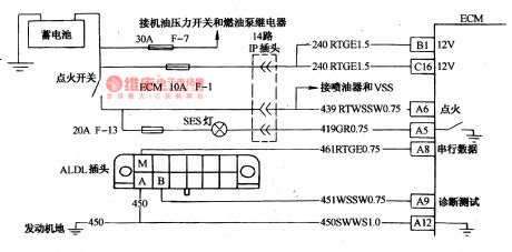
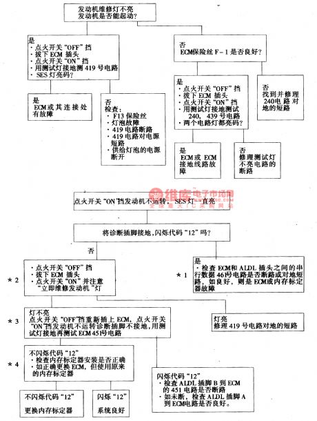
3.test on diagnosis circuitIn Figure 3 and Figure 4, to find out the fault with the help of fault diagnosis light (SES), we should know the diagnosis circuit is all right at first, if it is ,then the engine willbe still when the igniting switch is on, but the light is glowing. To diagnosis outlet ground connection in the above way, we should flash the code of 12 for 3 times at first , and then flash other codes. If others are all right,then flashthe code of 12repeatedly, the checking course is as follows.
(View)
View full Circuit Diagram | Comments | Reading(789)
Toy Or Sprots Model Controlled By Flashlight Circuit
Published:2011/5/17 5:49:00 Author:Robert | Keyword: Toy, Sprots Model, Flashlight
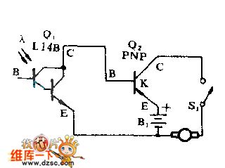
The flashlight has been installed two batteries. When irradiating the phototube Q1 with distance about 152.4cm (5 feet), the toy or sports model's motor could be started and can maintain running about 457.2cm (15 feet) in irradiation of normal room lamp light. Any PNP type power transistors Q2 arerequired to stand the model motor's flowing current. The battery is installed in the model.
(View)
View full Circuit Diagram | Comments | Reading(538)
Stepper Motor Control Experimental Circuit
Published:2011/5/17 5:46:00 Author:Robert | Keyword: Stepper Moto, Control, Experimental
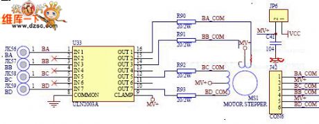
Learning the working principle and controlling methods of stopper motor and mastering some simple circuit-control and basic motor knowledge.
The Stepper Motor Control Experimental Circuit is shown below.
(View)
View full Circuit Diagram | Comments | Reading(1090)
Differential Combustible Gas Detector Circuit
Published:2011/5/17 5:45:00 Author:Robert | Keyword: Differential, Combustible Gas, Detector
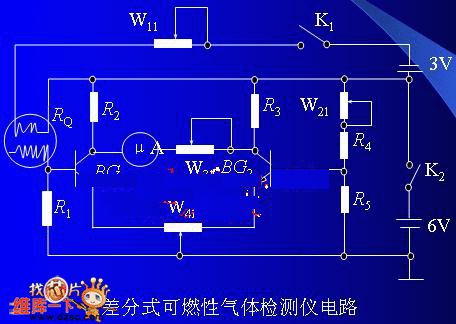
In this circuit, BG1 and BG2's values should be as same as possible and it is best to choose differential pairs. Using this differential circuit the sensitivity of detecting gas could be 100×10^-6.
The Differential Combustible Gas Detector Circuit is shown below.
(View)
View full Circuit Diagram | Comments | Reading(882)
Using TX05D Infrared Control Door Bell Circuit
Published:2011/5/12 23:43:00 Author:Robert | Keyword: Infrared Control, Door Bell
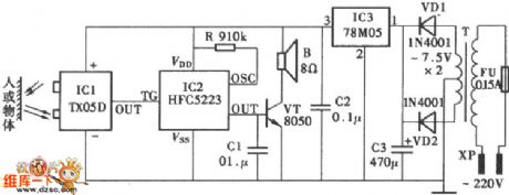
The Using TX05D Infrared Control Door Bell Circuit is shown below.
(View)
View full Circuit Diagram | Comments | Reading(1063)
Capacitive Humidity Sensor Application Circuit
Published:2011/5/17 21:42:00 Author:Robert | Keyword: Capacitive, Humidity Sensor, Application
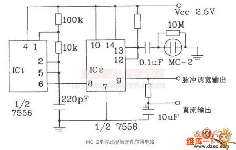
The Capacitive Humidity Sensor Application Circuit is shown below.
(View)
View full Circuit Diagram | Comments | Reading(939)
Timing Flash Circuit Driven By FET
Published:2011/5/12 23:44:00 Author:Robert | Keyword: Timing, Flash, FET
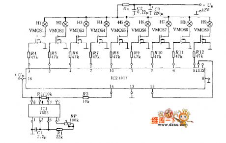
Using the circuit in the picture, it only needs a few components to make up a loop light timing control circuit. The circuit is made up by MOS time-base circuit 7555, CMOS decimal counter (pulse divider) 4017 and end-stage VMOS power transistor. The power transistor can control the lamp whose maximum current is 2A, and the resistance RV between lamp and power +VB is used for limiting current.
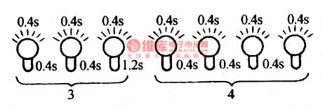
The time-base circuit's frequency is adjusted by the potentiometer RP (about 0.5~10Hz). The 9-stage loop register is controlled by the square wave output signal from the timing input port to change each output port to be high-voltage level in turn. Because the pin 11 is connected with the reset input pin 15, the coming of the tenth pulse would control the first lamp bright again.
(View)
View full Circuit Diagram | Comments | Reading(1084)
The flash sequence of code 34 of Daewoo
Published:2011/5/18 21:36:00 Author:Borg | Keyword: flash sequence, Daewoo
Fault code list:Code of 14--coolant temperature circuit(indicating high temperature)Code of 15--coolant temperature circuit(indicating low temperature)Code of 21--TPS circuit (high signal voltage )Code of 21--TPS circuit (low signal voltage )Code of 23--MAT sensor circuit (temperature is too low)Code of 24-- VVS circuitCode of 25-- MAT sensor circuit (temperature is too high)
(View)
View full Circuit Diagram | Comments | Reading(600)
The ABS circuit of Buick-Century
Published:2011/5/18 2:48:00 Author:Borg | Keyword: ABS, Buick-Century
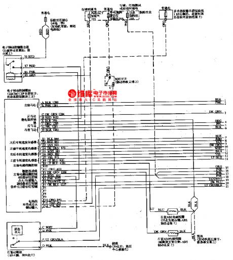
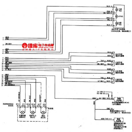
The ABS is used to control the range of slip rate between wheels and the ground when braking the car, which can prevent the wheel locking and slipping, so that the steering control and side-slipping can be avoided. When the sensor delivers the differentia between wheels and the car indicating the wheel is locked, the ABS computer will give order to activate the magnetic valve to reduce the pressure of the brake cylinder. The circuit is shown in Figure 1 and Figure 2.
Figure 1. The ABS system of Buick-Century
(View)
View full Circuit Diagram | Comments | Reading(1014)
AN8482SB-the integrated circuit of the 3-phase spindle motor driver
Published:2011/5/18 3:54:00 Author:Borg | Keyword: integrated circuit, 3-phase, motor driver
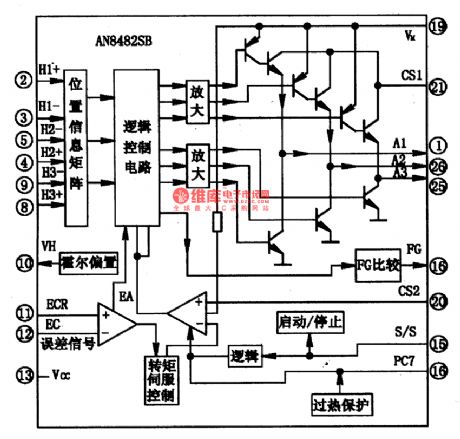
1.the internal circuitAN8482SB contains sub-circuits of Hall position information matrix, logic control, selective distributor, differentia amplifier, 3-phase motor driver, FG comparison and starting/stopping, in addition, it has has a functions of overhead protection. The internal circuit is shown in Figure 1.
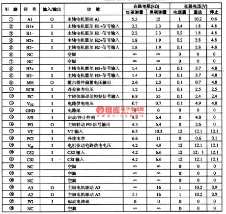
2.pin functions and dataAN8482SB is in flat 28-lead package with cooling fins, whose pin functions and data are listed in Table 1, and the data were got from tests on TCL DVD一250O.
(View)
View full Circuit Diagram | Comments | Reading(858)
AN8706FHQ-the integrated circuit of DVD front-end processor
Published:2011/5/18 3:40:00 Author:Borg | Keyword: integrated circuit, front-end processor
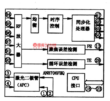
AN8706FHQ is an integrated circuit of DVD front-end processor produced by Panasonic especially for its CR2一DV3 DVD player.1.function featuresThe main function of AN8706FHQ is that it can convert the signals which are delivered and magnified by laser heads into synchronous RF digital signals, besides ,it also shifts the disc information read out by laser heads into focus error and track error signals for the sub-circuits. The internal circuit of it is as shown in Figure 1.
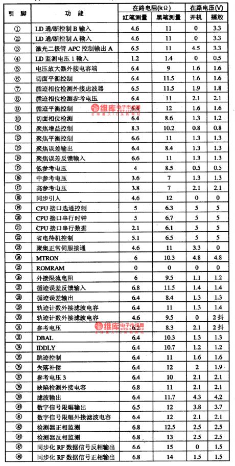
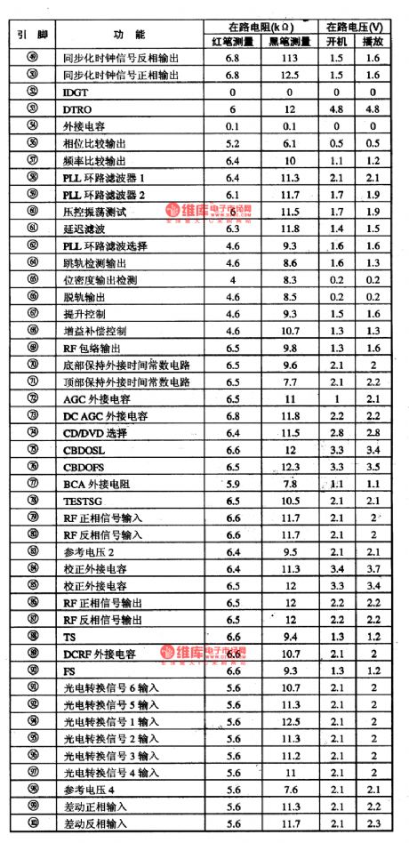
2.pin functions and dataThe pin functions and data are listed in Table 1.
(View)
View full Circuit Diagram | Comments | Reading(757)
| Pages:1852/2234 At 2018411842184318441845184618471848184918501851185218531854185518561857185818591860Under 20 |
Circuit Categories
power supply circuit
Amplifier Circuit
Basic Circuit
LED and Light Circuit
Sensor Circuit
Signal Processing
Electrical Equipment Circuit
Control Circuit
Remote Control Circuit
A/D-D/A Converter Circuit
Audio Circuit
Measuring and Test Circuit
Communication Circuit
Computer-Related Circuit
555 Circuit
Automotive Circuit
Repairing Circuit