
Circuit Diagram
Index 1854
Double limit value temperature control circuit
Published:2011/5/17 8:52:00 Author:TaoXi | Keyword: Double limit value, temperature control
The Double limit value temperature control circuit: (View)
View full Circuit Diagram | Comments | Reading(701)
Three-bit temperature controller circuit
Published:2011/5/17 8:50:00 Author:TaoXi | Keyword: Three-bit, temperature controller
Related components PDF download:
TCA965
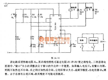
This circuit uses the thermistor RH, it's nonlinear characteristics can be changed into the linear characteristics by R1 and R2. In the three states of the relay control, the window size adjustment depends on the halfway point of the window and the half width. If the input voltage UE is in the window, the circuit is neither heating nor cooling. Otherwise, it should be heating or cooling. The tolerance is the window size or the mediate precision, it is adjusted by the potentiometer RP2. Because there must be the tolerance zone, so the precision may not infinitely improved.
(View)
View full Circuit Diagram | Comments | Reading(827)
Automatic temperature control circuit uses the temperature control application-specific integrated circuit
Published:2011/5/17 6:34:00 Author:TaoXi | Keyword: Automatic, temperature control, application-specific
Related components PDF download:
TC6209014KD-15690139015
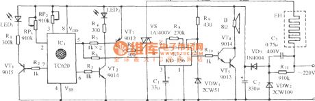
As the figure shows, this circuit is composed of the temperature sensing switch, the temperature upper-limit and lower-limit LED display circuit, the SCR control circuit, the analog audio circuit and the AC step-down rectifier circuit.etc. This temperature control circuit can control the temperature automatically between the upper-limit and lower-limit, the temperature measurement precision is ±3℃, the temperature controlling effect is good, also it can undertake the overtemperature instruction. (View)
View full Circuit Diagram | Comments | Reading(1484)
using RCM-1A/1B wireless remote control spotlight circuit
Published:2011/5/17 9:36:00 Author:Lena | Keyword: wireless, remote control, spotlight

(View)
View full Circuit Diagram | Comments | Reading(604)
Water temperature automatic controller circuit
Published:2011/5/17 9:18:00 Author:TaoXi | Keyword: Water temperature, automatic controller
The Water temperature automatic controller circuit is as shown: (View)
View full Circuit Diagram | Comments | Reading(663)
Tropical fish tank water temperature automatic heating controller circuit
Published:2011/5/17 9:24:00 Author:TaoXi | Keyword: Tropical fish tank, water temperature, automatic heating controller
The Tropical fish tank water temperature automatic heating controller circuit is as shown: (View)
View full Circuit Diagram | Comments | Reading(702)
Temperature measurement circuit uses the operational amplifier as the differential amplifier
Published:2011/5/17 18:54:00 Author:TaoXi | Keyword: Temperature measurement, operational amplifier, differential amplifier
Related components PDF download:741BC107BC360BSY86 (View)
View full Circuit Diagram | Comments | Reading(582)
Measurement and temperature control circuit uses the infrared group inspection device
Published:2011/5/17 19:07:00 Author:TaoXi | Keyword: Measurement, temperature control, infrared group inspection
Related components PDF download:
BC109BCY71
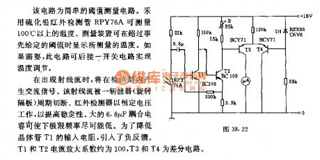
The ray stream will produces the AC signal in the detector. And this ray stream will be cut off by the chopper's (rotary separator) cycle. The infrared detector is working with the constant voltage to improve the stability. The big 6.8pF coupling capacitor can make the floor frequency lower and lower. In order to reduce the transistor T1's input resistance, we pull in the negative feedback. T1 and T2's current amplification coefficient is about 100, T3 and T4 are the differential circuit.
(View)
View full Circuit Diagram | Comments | Reading(521)
LCD electronic thermometer circuit
Published:2011/5/17 8:18:00 Author:TaoXi | Keyword: LCD, electronic thermometer
Related components PDF download:
ICL7106CD4036
The LCD electronic thermometer
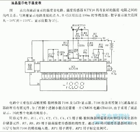
The LCD electronic thermometer circuit is as shown. The temperature sensor KTY10 has good linear relationship
between temperature - resistance, and you can connect point A and point B (Measurement display circuit) with 100m wire, the digital display range is -50℃ to +150℃, the display digits is 3 1/2.
This circuit includes the high precision mold - digital converter 7106 and the LCD monitor. The 7106 includes all the active components that can be used to control the 3 1/2 LCD. In order to control the decimal point, you need one piece of CMOS circuit CD4030. As a result of the LCD, the whole circuit's power consumption is small.
(View)
View full Circuit Diagram | Comments | Reading(2817)
The diagnosis circuit of Daewoo ESPERO fault code of 15
Published:2011/5/18 1:33:00 Author:Borg | Keyword: diagnosis circuit, Daewoo ESPERO
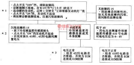
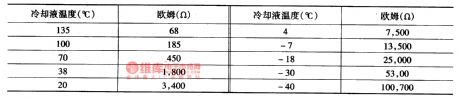
The code of 15 means that the signal voltage of coolant temperature sensor is high --indicating low temperature, whose change regulation of resistance and signal voltages is the same with the code of 14, and its influence range is also the same with the code of 14. Its circuit is shown in Figure 16 and Figure 4.
*1 is used to detect whether the fault is actual or caused by interrupted factors, the conditions of generating the fault is: the engine has run for more than 1min; the signal voltage indicates that the temperature of coolant is lower than -37℃, which is opposite to the code of 15 which means warm engine .
(View)
View full Circuit Diagram | Comments | Reading(719)
The instrument, indicator and warning lamp circuit of Buick-Century
Published:2011/5/18 2:16:00 Author:Borg | Keyword: instrument, indicator, warning lamp, Buick-Century
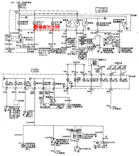
The instrument, indicator and warning lamp circuit of Buick-Century is like that of other cars, the instruments include coolant thermometer, fuel gauge, engine rotating speed meter, speedometer, and it is also fixed with a voltmeter.
There are many warning lamps, such as the oil pressure warning lamp, charging indicator, brake indicator, high beam indicator, left-steering indicator, right-steering indicator, seatbelt indicator, cruise indicator, tail gate indicator, air bag indicator, low drive indicator and anti brake lock indicator, etc. (View)
View full Circuit Diagram | Comments | Reading(967)
BA1106-the Dolby B noise reduction integrated circuit
Published:2011/5/17 4:56:00 Author:Borg | Keyword: Dolby, noise reduction
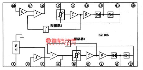
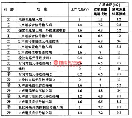
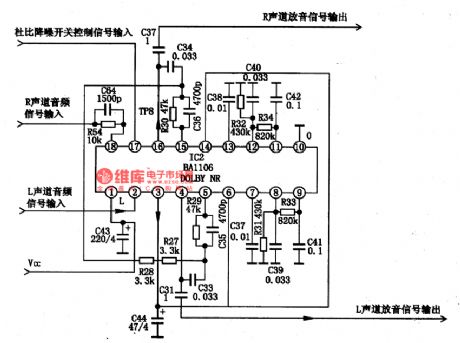
BA1106 is an Dolby B noise reduction integrated circuit produced by Toyo, Corp., Japan, which is widely used in walk-man, domestic stereos and car stereos.1.the internal circuit and pin functions of BA1106BA1106 consists of magnifier, adder, amplitude limiter and variable resistance, whose internal circuit is shown in Figure 1 and whose pin functions and working data are listed in Table 1.
Figure 1 the internal circuit of BA1106
2.the typical application circuit of BA1106The typical application circuit of BA1106 shown as follows
(View)
View full Circuit Diagram | Comments | Reading(4680)
The transmission SIL circuit fault detection of Daewoo ESPERO
Published:2011/5/17 2:33:00 Author:Borg | Keyword: SIL, fault detection, Daewoo ESPERO
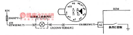
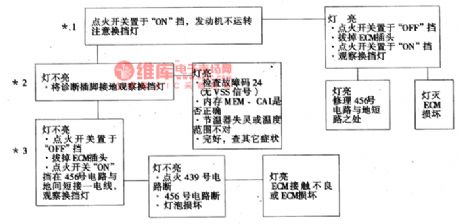
In the Daewoo ESPERO of hand transmission, SIL can remind the driver to shift the transmission to another gear according to the rotating speed and load of the engine and the car speed, by which the engine was made sure to consume the minimum oil. The shift indicator light is on the dashboard, which is lighted by the ECM driver.
*1.There the SIL should be off, if not, that means the No. 456 circuit is short or ECM is broken.*2.When the detection plug connects with the ground, ECM should connect No.456 with the earth and the SIL should light.
(View)
View full Circuit Diagram | Comments | Reading(754)
Twilight light control switch circuit
Published:2011/5/18 19:50:00 Author:John | Keyword: light control switch
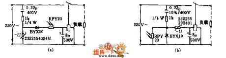
This switch takes action within the above or below of a certain illumination. The typical application is the automatic switch for the early morning and evening lights. Figure (a) and (b) show the circuits which adopt two cadmium iodide photosensitive electric resistors with RPY20 . And the resistors are all directly powered by alternating current. 1KΩ resistance is used to reduce current ripple. And the resistance of relay coil is 21.8Ω. The pull-in voltage is 45V and the release voltage is 18V. And the contacted electrolytic capacitors cooperate to constitute the RC of 0.1S. Such is to reduce the short light flashes, to smooth output DC voltage of the diode rectifier and to prevent fibrillation of the relay.
(View)
View full Circuit Diagram | Comments | Reading(1213)
Plastic bag sealing machine circuit diagram 2
Published:2011/5/18 19:50:00 Author:Lucas | Keyword: Plastic bag , sealing machine
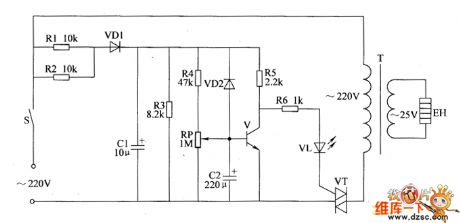
The plastic bag sealing circuit is composed of power supply circuit and heating control circuit, the circuit is shown as the chart. Power supply circuit is composed of the power button S, resistors R1, R2, rectifier diode VD1 and filter capacitor C1. Heating control circuit consists of transistor V, thyristor VT, resistors R4 ~ R6, potentiometer RP, power transformer T, light-emitting diode VL and strip heater EH. power button S is controlled by the heating operating handle. When people use it, the plastic bag should be pressed on the strip heater EH, and after pressing the operating handle, the AC 220V voltage is limited and bucked by R1, rectified by VD1 and filtered by C1, then it provides DC operating power for V by R4, RP and R5.
(View)
View full Circuit Diagram | Comments | Reading(6608)
Magnetic stirring apparatus circuit diagram 1
Published:2011/5/18 0:28:00 Author:Lucas | Keyword: Magnetic stirring apparatus
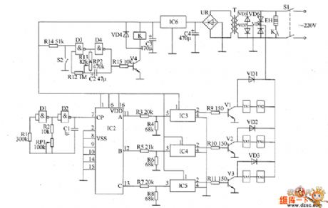
The magnetic stirring apparatus circuit is composed of the power circuit, heating control circuit, clock oscillator, pulse distribution controller and the solenoid controller, the circuit is shown as the chart. Power circuit is composed of the power switch S1, the power transformer T, rectifier bridge pile UR, three-terminal voltage regulator integrated circuit IC6 and filter capacitor C3, C4.Heating control circuit consists of resistors R12 ~ R15, potentiometer RP2, heating control switch S2, capacitor C2, NAND integrated circuit IC1 (D1 ~ D4) and the onternal D3, D4, transistor V4, diode VD4, and relay K, electric heater EH. (View)
View full Circuit Diagram | Comments | Reading(2621)
Motor electronic speed controller circuit diagram 4
Published:2011/5/18 6:51:00 Author:Lucas | Keyword: Motor , electronic speed controller
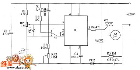
The motor speed controller circuit consists of power circuit, timing control / trigger pulse generator circuit and control implementation circuit, the circuit is shown as the chart. Power supply circuit consists of step-down capacitor C5, voltage regulator diode VS, rectifier diode VD2, filter capacitor C1. Timer control / trigger pulse generator circuit is composed of the time-base integrated circuit IC, the control switch S1, timer / voltage selecting switch S2, resistors R1 ~ R3, potentiometers RP1, RP2, capacitors C2 ~ C4. Control implementation circuit is composed of the resistor M and thyristor VT. AC 220V voltage is bucked by C5, stabilized by resistor R5, VS, rectified by VD2 and filtered by C1 to provide 121V (Vcc) DC working voltage for IC. R1 ~ R5 use 1/4W carbon film resistors or metal film resistors.
(View)
View full Circuit Diagram | Comments | Reading(4374)
Motor electronic speed controller circuit diagram 5
Published:2011/5/18 6:43:00 Author:Lucas | Keyword: Motor , electronic speed controller
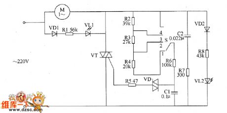
The motor electronic speed controller circuit consists of intergranular tube VT, diode VD1, VD2, bidirectional trigger diode VD, LEDs VL1, VL2, capacitors GI, C2, resistors R1 ~ R8, speed control switch S, motor M and so on, the circuit is shown as the chart. Changing the gear of S speed switch can change the charging and discharging rate of capacitor C1, thereby the thyristor conduction angle of thyristor VT is changed. The voltage on the two ends of C1 can trigger VT and make it turn on by VD, the AC voltage across the motor M is controlled by changing the conduction angle, thus the M's running speed is changed. VL1 and VL2 are the working status indicator LEDs. When S is placed on the 1 block, VL2 is lit; when the S is placed on the 4 block, VL1 is lit.
(View)
View full Circuit Diagram | Comments | Reading(1226)
INA217 Signal And Power Supply Basic Connection Circuit
Published:2011/5/17 21:42:00 Author:Robert | Keyword: Signal, Power Supply, Basic Connection
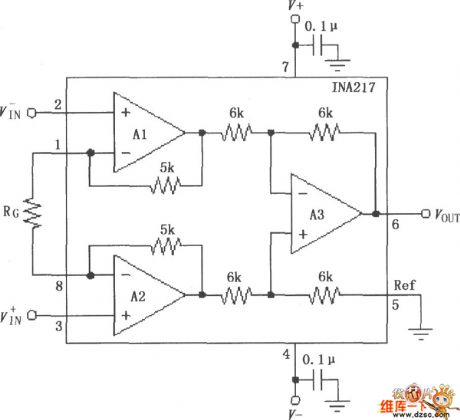
The INA217 Signal And Power Supply Basic Connection Circuit is shown below.
(View)
View full Circuit Diagram | Comments | Reading(758)
Motor electronic speed controller circuit diagram 6
Published:2011/5/18 6:20:00 Author:Lucas | Keyword: Motor , electronic speed controller
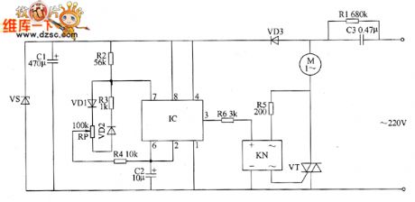
The motor speed controller circuit consists of power circuit, ultra-low frequency oscillator circuit and control implementation circuit, the circuit is shown as the chart. Power supply circuit consists of step-down capacitor C3, discharging resistor R1, rectifier diode VD3, filter capacitor C1 and Zener diode VS. Ultra-low frequency oscillator is composed of time-base integrated circuit, resistor R2 ~ R4, potentiometer RP, capacitors C2 and diodes VD1, VD2. Control implementation circuit is composed of a solid state relay KN (SSR), thyristor VT and resistors R5, R6. AC 220V voltage is bucked by C3, rectified by VD3, filtered by C1 and stabilized by vs to provide +12 V operating voltage for IC. When ultra-low-frequency oscillator gets power and works, the IC output frequency from pin 3 of IC is about 1Hz ultra-low frequency pulse signal.
(View)
View full Circuit Diagram | Comments | Reading(2142)
| Pages:1854/2234 At 2018411842184318441845184618471848184918501851185218531854185518561857185818591860Under 20 |
Circuit Categories
power supply circuit
Amplifier Circuit
Basic Circuit
LED and Light Circuit
Sensor Circuit
Signal Processing
Electrical Equipment Circuit
Control Circuit
Remote Control Circuit
A/D-D/A Converter Circuit
Audio Circuit
Measuring and Test Circuit
Communication Circuit
Computer-Related Circuit
555 Circuit
Automotive Circuit
Repairing Circuit