
Circuit Diagram
Index 1834
The protector circuit of 555 air-conditioning
Published:2011/5/29 21:28:00 Author:Borg | Keyword: protector circuit, air-conditioning
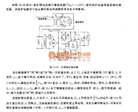
When the air-conditioner is at the wind gear(or cold gear) and it is on, as the voltage on C2 can not mutate, so 555 is offset, J2 keeps still, J2-2 is off, the compressor gets no power and can't start. When C2 engages in charging by R1, after the delaying time td=1.1R1C2, which is about 3min, the LEV of 6-pin rises to 2/3VDD, and that makes 555 reset, J2 pull in and the compressor gets power. At the moment, J1 pulls in and gets power, J1-1 and J1-4 close, J1-1 and J1-3 cut off, and the 555 is in a compelled reset state, the 3-pin is in a low LEV which makes J2-2 to be connected. (View)
View full Circuit Diagram | Comments | Reading(558)
Power-supply of adjustable DC steady voltage part 9
Published:2011/5/29 20:15:00 Author:Ariel Wang | Keyword: adjustable, DC , steady voltage
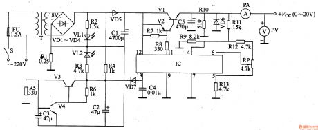
Over current protected circuit is made up by the 13th foot internal circuit of IC,transistor V3,V4,resistor R1,R3-R6,capacitor C2-C4,diode VD7 and LED VL2.When switch S of power-supplyis gottenthrough,the 220V AC voltage is dropped down through T,commutated through VDl-VD4.It lights VL1 up through R2.It is connected to emitter of V3 through R4.And it lights VL2 up at the same time.It is isolated and filtered through VD5 and C1.It generates the voltage of around +23V voltage. And it is connected to the 12th foot of IC and collector of V1. The +23V voltage is regulated and adjusted through circuit.It outputs steady DC voltage from the emitter of V1. You can adjust the resistance of RP,in order to make the output voltage change continuously between 0-+20V.
(View)
View full Circuit Diagram | Comments | Reading(3958)
Power-supply of adjustable DC steady voltage part 7
Published:2011/5/29 20:16:00 Author:Ariel Wang | Keyword: adjustable, DC, steady voltage
(View)
View full Circuit Diagram | Comments | Reading(684)
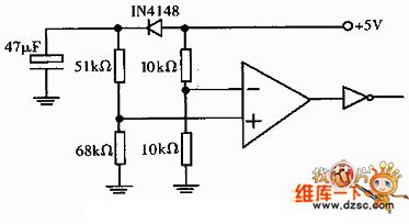
the reset circuit of improved comparator
Published:2011/5/28 18:22:00 Author:Ariel Wang | Keyword: reset, improved, comparator
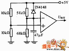
The reset circuit of improved comparator is as the chart below:
(View)
View full Circuit Diagram | Comments | Reading(579)
the compound circuit of basic comparator
Published:2011/5/28 18:26:00 Author:Ariel Wang | Keyword: compound circuit, basic, comparator
The compound circuit of basic comparator is as the chart below:
(View)
View full Circuit Diagram | Comments | Reading(631)
the circuit of power supply isolation
Published:2011/5/28 18:34:00 Author:Ariel Wang | Keyword: power supply, isolation
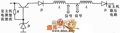
The circuit of power supply isolation is as the chart below:
(View)
View full Circuit Diagram | Comments | Reading(453)
Power-supply of adjustable DC steady voltage part 13
Published:2011/5/29 20:14:00 Author:Ariel Wang | Keyword: adjustable, DC, steady voltage
&nbs (View)
View full Circuit Diagram | Comments | Reading(854)
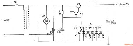
power-supply circuits-fixed of numerical control and DC part 1
Published:2011/5/29 20:13:00 Author:Ariel Wang | Keyword: mumerical control, DC, circuits-fixed
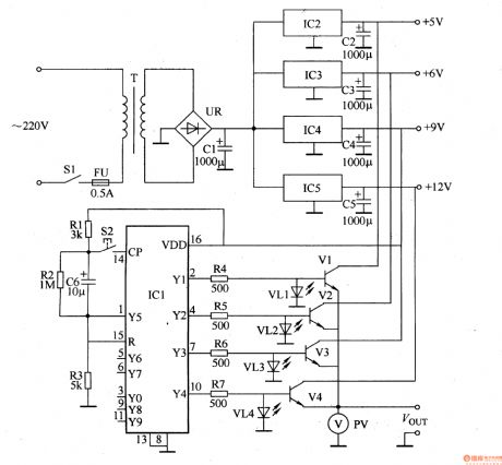
After SI is being connected, 220VACvoltage is dropped down through T, commutated through UR and filtered through C1.It generates +18V DC voltage. The voltage is steady through IC2,IC3,IC4 and IC5. Then it generates the voltage of 5V,+6V,+9V and +l2V. These four groups are put on V1-V4 collectors. The voltage of +gV is being as working power supply as IC. After ICl electrified and reset, the YO edge(3 feet)is high power level output,Yl-Y9 is low power level output. Press S2,the CP edge (14 feet) will output a bigger counting pulse. The Yl egde wil output high power level,while YO edge turns back to low power level. Press S2 continuously,the YO-Y4 edge of ICl will output high power level one by one.
(View)
View full Circuit Diagram | Comments | Reading(973)
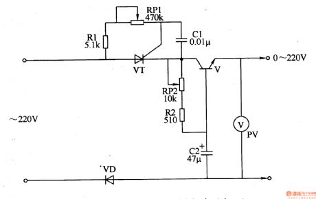
power-supply circuit-fixed of adjustable DC
Published:2011/5/25 0:10:00 Author:Ariel Wang | Keyword: circuit-fixed, adjustable, DC
(View)
View full Circuit Diagram | Comments | Reading(983)
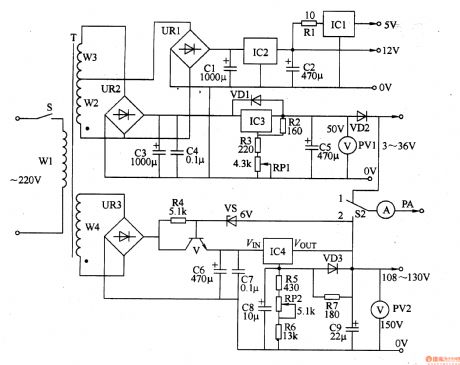
Power-supply of adjustable DC steady voltage
Published:2011/5/25 23:26:00 Author:Ariel Wang | Keyword: adjustable, DC, steady voltage
(View)
View full Circuit Diagram | Comments | Reading(1035)
Measuring Bridge Amplifier Circuit
Published:2011/5/21 20:30:00 Author:Robert | Keyword: Measuring Bridge, Amplifier
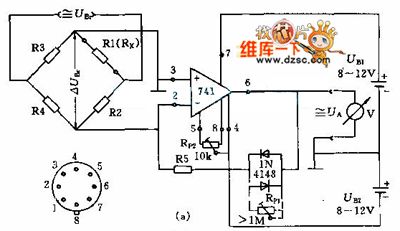
In the circuit (a) the measuring bridge is made up by R1~R4 resistances. The output voltage URr can be DC or AC voltage (maximum 100kHz). If it is AC voltage it can use the coupling capacitor (picture b). And it can use high resistance in these two cases.
(View)
View full Circuit Diagram | Comments | Reading(594)
The MC3362 Low-Power Narrow-Band FM Receiver Integrated Circuit Typical Application Circuit
Published:2011/5/21 20:00:00 Author:Robert | Keyword: Low-Power, Narrow-Band, FM, Receiver, Integrated, Application
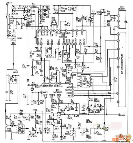
The MC3362 is produced by Motorola which is a low-power narrow-band FM receiver integrated circuit. It is widely used in narrow-band voice and data communications in the FM receiver circuits. The MC3362 integrated circuit has two FM transformation oscillators, mixers etc. which means it has a complete FM narrow-band receiver circuit. The decoder typical application's circuit composed of MC3362 integrated circuit is shown in the pocture below.
(View)
View full Circuit Diagram | Comments | Reading(4589)
Low-Frequency Modulator Circuit
Published:2011/5/21 8:17:00 Author:Robert | Keyword: Low-Frequency, Modulator
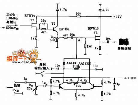
This circuit is a amplitude modulator circuit. The T1 and T2 transistors are used to separate the modulator part. The low-frequency signal has the best value when the potentiometer RP1 is adjusted to about 500mV. The low-frequency then passes the isolation stage T3 which would output low-frequency modulation signals. The low-frequency amplitude is adjusted by the potentiometer RP2.
(View)
View full Circuit Diagram | Comments | Reading(690)
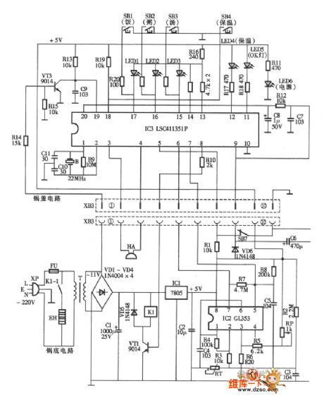
Midea CFXB40-32 Rice Cooker circuit
Published:2011/5/23 20:53:00 Author:John | Keyword: Rice Cooker
Midea CFXB40-32 Rice Cooker circuit is shown below.
(View)
View full Circuit Diagram | Comments | Reading(1503)
FM transmitter 07 circuit
Published:2011/5/23 20:54:00 Author:John | Keyword: FM transmitter
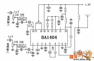
FM transmitter 07 circuit is shown below.
(View)
View full Circuit Diagram | Comments | Reading(487)
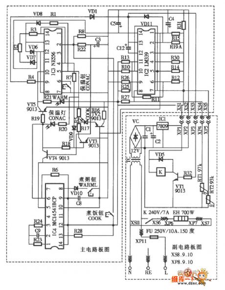
HeyGey GDS65-C computer type multi-use rice cooker circuit
Published:2011/5/23 20:59:00 Author:John | Keyword: multi-use rice cooker
HeyGey GDS65-C computer type multi-use rice cooker circuit is shown below.
(View)
View full Circuit Diagram | Comments | Reading(812)
Capacitance feedback oscillator circuit
Published:2011/5/23 21:01:00 Author:John | Keyword: Capacitance feedback oscillator
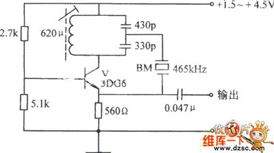
Capacitance feedback oscillator circuit is shown below.
(View)
View full Circuit Diagram | Comments | Reading(512)
Crystal diode DDZX9689TTS internal circuit
Published:2011/5/23 21:03:00 Author:John | Keyword: Crystal diode
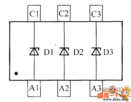
Crystal diode DDZX9689TTS internal circuit is shown below.
(View)
View full Circuit Diagram | Comments | Reading(512)
Toyota Vios ABS control circuit
Published:2011/5/23 21:04:00 Author:John
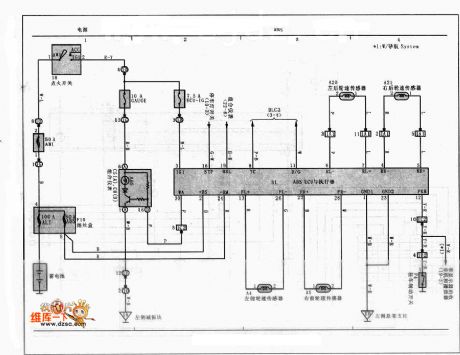
Toyota Vios ABS control circuit is shown below.
 (View)
View full Circuit Diagram | Comments | Reading(4354)
filter oscillation circuit
Published:2011/5/23 21:32:00 Author:John | Keyword: filter

Filter oscillation circuitis shown below.
(View)
View full Circuit Diagram | Comments | Reading(486)
| Pages:1834/2234 At 2018211822182318241825182618271828182918301831183218331834183518361837183818391840Under 20 |
Circuit Categories
power supply circuit
Amplifier Circuit
Basic Circuit
LED and Light Circuit
Sensor Circuit
Signal Processing
Electrical Equipment Circuit
Control Circuit
Remote Control Circuit
A/D-D/A Converter Circuit
Audio Circuit
Measuring and Test Circuit
Communication Circuit
Computer-Related Circuit
555 Circuit
Automotive Circuit
Repairing Circuit