
Circuit Diagram
Index 1827
Index operation circuit
Published:2011/5/26 2:38:00 Author:Christina | Keyword: Index, operation
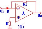
The index operation circuit is the inverse operation of the logarithmic operation, you can exchange the index operation circuit's diode (transistor) and the resistance R. The circuit is as shown:
By using the logarithm and index operations and the proportions, also the differential operation circuit, we can form the multiplication or division operation circuit and other nonlinear operation circuits. (View)
View full Circuit Diagram | Comments | Reading(526)
AD574A and the SCM interface circuits
Published:2011/5/26 2:27:00 Author:Christina | Keyword: SCM, interface
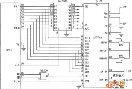
The SCM interface circuit which is composed of the AD574A is as shown. This circuit uses the AD574A type 12-bit gradually comparative type A/D converter, also it has the mixed integration type conversion chip which is composed of two pieces bipolar type circuit, the precision and speed is high, it is one kind of A/D converter that can be used in wide range of applications, also the interface circuit which is composed of it. (View)
View full Circuit Diagram | Comments | Reading(1093)
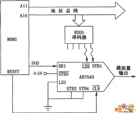
Long distance transmission interface circuit (AD7543)
Published:2011/5/26 2:13:00 Author:Christina | Keyword: Long distance, transmission, interface circuit
View full Circuit Diagram | Comments | Reading(560)
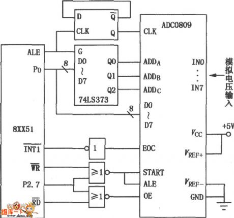
SCM interface circuit (ADC0809)
Published:2011/5/26 2:14:00 Author:Christina | Keyword: SCM, interface circuit
View full Circuit Diagram | Comments | Reading(542)
The voltage adjuster and contrast control circuit
Published:2011/5/25 22:19:00 Author:Christina | Keyword: voltage adjuster, contrast control
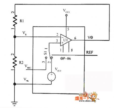
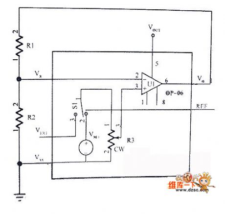
The voltage regulator circuit can be used to get a proper LCD display driver voltage. This voltage is decided by the R1 and R2. The voltage regulator circuit is as shown in the following figure.
The voltage adjustment has 32 contrast ratio stages. When you are using the contrast ratio to control the functions, the voltage regulator needs to open by the power control instruction. The contrast ratio control circuit is as shown. (View)
View full Circuit Diagram | Comments | Reading(683)
Oil pressure display circuit
Published:2011/5/26 1:33:00 Author:Christina | Keyword: Oil pressure, display circuit
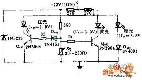
The sensor changes the oil pressure into the variable resistance RT. The variation of RT changes the bias voltage of each crystal transistor, the three LEDs (red, yellow and green) light in different positive biases. So we can ensure that every time there is only one light-emitting diode shining to indicate the corresponding hydraulic.
(View)
View full Circuit Diagram | Comments | Reading(608)
Long tail type differential amplifier circuit
Published:2011/5/25 21:50:00 Author:Christina | Keyword: Long tail, differential amplifier
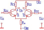
As the right figure shows, the differential-mode gain is 48dB, the common mode rejection ratio is 67dB,Ui1=5V,Ui2=5.01V, try to know the output voltage Vo.
(View)
View full Circuit Diagram | Comments | Reading(570)
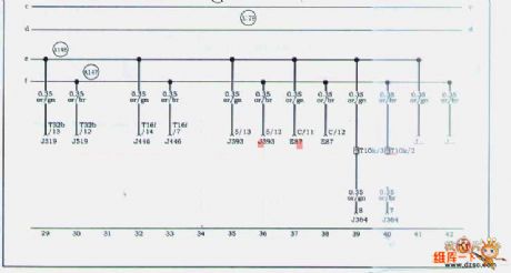
Audi A4 saloon car CAN-BUS circuit (1)
Published:2011/5/25 20:51:00 Author:Christina | Keyword: Audi, A4, saloon car

Audi A4 saloon car CAN-BUS circuit (1) is as shown:
(View)
View full Circuit Diagram | Comments | Reading(1643)
FET FM wireless microphone circuit
Published:2011/5/26 6:52:00 Author:Christina | Keyword: FET, FM, wireless microphone
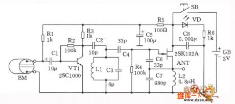
The FET FM wireless microphone circuit is as shown in this figure. This circuit uses the 2SCl000 which has the high amplification coefficient as the microphone amplification stage. The MOSFET 2SKl92A has the functions of oscillation and modulation output. The oscillation frequency is decided by the coil Ll and the parallel capacitor 6pF, by adjusting the microchip of the LI, the oscillation frequency can be changed in the range of 76MHz to 90MHz. At last, you use a ethylene line as the antenna and directly output from the FET's source electrode. In order to prevent the interference between different stages, we use the l00Ω, 47μF capacitance to form the decoupling circuit. When the circuit is working, the light-emitting diode VD turns on. The output port of the circuit do not need the buffer stage to work.
(View)
View full Circuit Diagram | Comments | Reading(1922)
Simple voltage control oscillator circuit
Published:2011/5/25 19:16:00 Author:Christina | Keyword: Simple, voltage control, oscillator
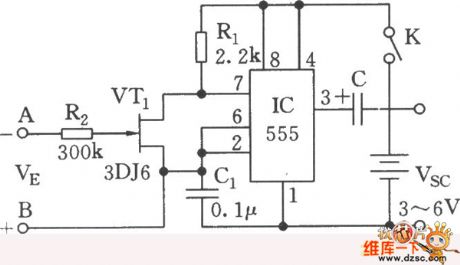
As the figure shows, the circuit uses the 555 and the MOSFET 3DJ6 as the core to form the controllable multivibrator. When you add the control voltage VK to the A and B ends, the 3DJ6's equivalent resistance RDS between the drain port and the source port will change, so the oscillation frequency of 555 changes too. And this circuit can be used in the applications of V/F conversion and tone recognition. (View)
View full Circuit Diagram | Comments | Reading(993)
2X12W integrated amplifier TDA1521 application circuit
Published:2011/5/25 19:06:00 Author:Christina | Keyword: 2X12W, integrated amplifier, application circuit
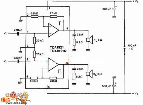
Figure: 2X12W integrated amplifier TDA1521 application circuit
(View)
View full Circuit Diagram | Comments | Reading(1268)
TDA1521 practical making miniature amplifier circuit
Published:2011/5/25 19:10:00 Author:Christina | Keyword: practical making, miniature, amplifier
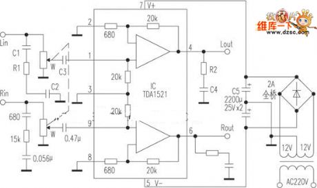
Figure: TDA1521 practical making miniature amplifier circuit
(View)
View full Circuit Diagram | Comments | Reading(1443)
Audi A4 saloon car CAN-BUS circuit (3)
Published:2011/5/25 19:08:00 Author:Christina | Keyword: Audi, A4, saloon car, CAN-BUS
The Audi A4 saloon car CAN-BUS circuit (3) is as shown:
(View)
View full Circuit Diagram | Comments | Reading(2456)
555 automatic speed governor circuit
Published:2011/5/19 22:11:00 Author:Christina | Keyword: automatic speed governor
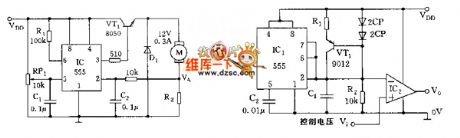
The circuit is as shown, the motor automatic speed governor circuit is composed of the 555 trigger and a switch tube. R7 and the motor is tandem connection to form the sampling circuit. In the motor regulation speed, the sampling voltage VA<1/3VDD, 555 sets, VT1 conducts and the motor gets power to work; when the speed is overrun, VA>1/3VDD, because the connection of R1, the 555 resets, the VT1 cuts off and the motor has no power, when VA<1/3VDD, the 555 sets, VT1 conducts and the motor gets power to work. (View)
View full Circuit Diagram | Comments | Reading(491)
The oscillator circuit with the independent adjustable charging and discharging time
Published:2011/5/25 19:03:00 Author:Christina | Keyword: oscillator, circuit, independent adjustable, charging, discharging, time
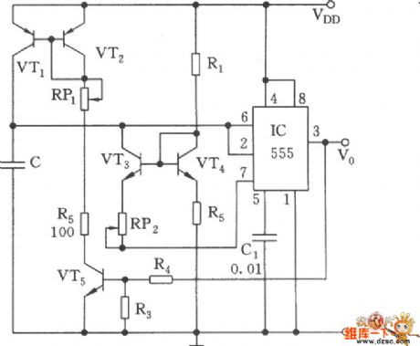
As the figure shows, the adjustment of common 555 multivibrator's charging and discharging time will influence each other. This circuit uses the mirror current source mode to keep the independence of the capacitance C's charging loop and discharging loop, and this circuit ensures the linearity of the charging and discharging. At the beginning, the output is the high level, VT5, VT2 and VT1 conduct, C is charged by VT1's constant-current, when VT1 has the 2/3VDD threshold level, 555 sets, pin-3 has the low level, and VT5 cuts off. C is discharged by the VT3 and IC's discharging tube, when the voltage of C is 1/3VDD, 555 sets. This cycle goes round and round to form the oscillation. (View)
View full Circuit Diagram | Comments | Reading(623)
Hitachi F1 microchip power supply circuit
Published:2011/5/25 6:18:00 Author:Christina | Keyword: Hitachi, F1, microchip, power supply
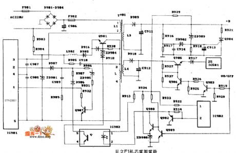
The Hitachi F1 microchip power supply circuit is as shown:
(View)
View full Circuit Diagram | Comments | Reading(1697)
BMW 528e series circuit in 1988
Published:2011/5/19 20:50:00 Author:Christina | Keyword: BMW, 1988
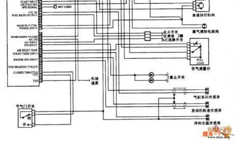
The BMW 528e series circuit in 1988:
(View)
View full Circuit Diagram | Comments | Reading(530)
The power supply circuit of 555 multi-function fridges (1)
Published:2011/5/30 22:36:00 Author:Borg | Keyword: power supply circuit, multi-function fridges
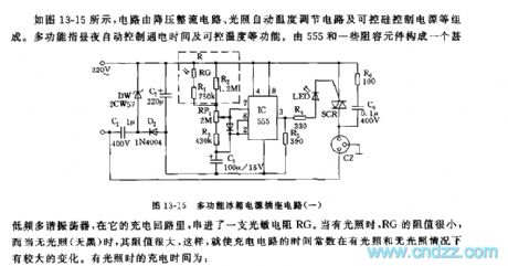
See as Figure 13-15, the circuit consists of the step-down rectifier circuit, lighting auto temperature adjusting circuit and controllable silicon control circuit, etc. The multi-function here means auto control of conducting time day and night, and controllable temperature, etc. 555 and some RC-components form a very low multi-resonate oscillator, in the oscillator circuit, a LDR is series connected. When there is light, the resistance of RG is very small; and when it dark outside, the resistance is very large, therefore, the time constant of the charging circuit changes a lot in the bright and dark environments. (View)
View full Circuit Diagram | Comments | Reading(557)
The power supply outlet circuit of 555 multi-function fridges (2)
Published:2011/5/30 22:58:00 Author:Borg | Keyword: power supply outlet, multi-function fridge
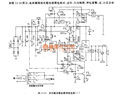
See as Figure 13-16, the fridge outlet includes sub-circuits of power-off time delay, over/low voltage warning,over/low voltage adjusting and temperature indication, etc. when mains voltage is higher than 245v or lower than 180v, the output voltage will be adjusted to about 220V; when the power is off, it will buzz.
RP1,RP2,F1,F2,F3 and so on consist a over/low/off power detection circuit, IC1 is connected as a Schmidt trigger. When it's over/low/off power, the output terminal of IC1 will be in a low LEV, VT5 is conducting, which makes the oscillator, consisting of IC2,R10,RT and C5, work.
(View)
View full Circuit Diagram | Comments | Reading(634)
The infrared remote control circuit of 888 domestic fans(2)
Published:2011/5/30 22:19:00 Author:Borg | Keyword: remote control, 888 domestic fans
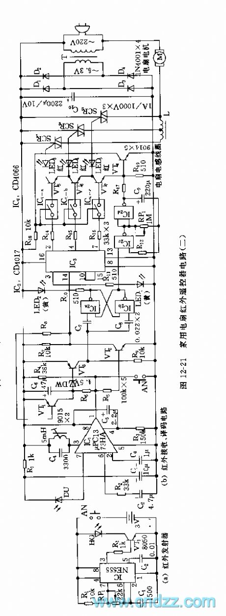
The model of infrared receiving pipe is coupled with the emitting pipe, the selection of wave length and light power should be noticed. IC1 is fixed with the special infrared receiving chip μPC1373 of color TV remote controls, when L and C4 circuits are modulated at the central frequency of 38kHz, an infrared pulse signal is received, and after magnification, detection and rectification by IC1, a low-LEV signal is output, then VT2 is blocked, and the high LEV signal of c pole is added to the input terminal of IC3 clock, then the clock starts to count, and Q1(2-pin) generates a high LEV pulse, the electric IC4-a and VT5 are conducting.
(View)
View full Circuit Diagram | Comments | Reading(742)
| Pages:1827/2234 At 2018211822182318241825182618271828182918301831183218331834183518361837183818391840Under 20 |
Circuit Categories
power supply circuit
Amplifier Circuit
Basic Circuit
LED and Light Circuit
Sensor Circuit
Signal Processing
Electrical Equipment Circuit
Control Circuit
Remote Control Circuit
A/D-D/A Converter Circuit
Audio Circuit
Measuring and Test Circuit
Communication Circuit
Computer-Related Circuit
555 Circuit
Automotive Circuit
Repairing Circuit