
Circuit Diagram
Index 592
Carat poured signal generator circuit
Published:2011/8/6 8:04:00 Author:nelly | Keyword: Carat poured, signal, generator
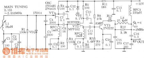
The Carat poured signal generator circuit is as shown. VTl is the variable LC oscillator formed by the typical high-stable Carat poured circuit. The capacity of the capacitance C4 and C5 is very large, and capacitance C4 and C5 can decide the feedback coefficient. The short flutter rate of drift, which is caused by the capacitance change, can be reduced by this carat poured signal generator.
(View)
View full Circuit Diagram | Comments | Reading(702)
Automatic Lighting Doorbell Circuit
Published:2011/8/5 9:14:00 Author:Robert | Keyword: Automatic, Lighting, Doorbell
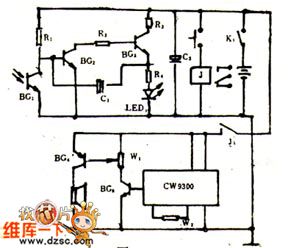
When in the night and the veranda also has not light, the doorbell's button is hard to find, especially for the new visitors. They could only knock the door. If adding a LED on the doorbell button switch, and the LED would automatically flash in the night. And it would automatically shut down in the day. This would provide the convenience for the visitors.The picture 1 shows the automatic lighting doorbell circuit.When the power switch K1 is closed, the phototransistor BG1's resistance would be reduced as it is under the light in the day. And the BG2 tube's base polar's voltage would also be reduced to make the BG2, BG3 be not conducted. Then the circuit would stop workng and the LED would not flash.
(View)
View full Circuit Diagram | Comments | Reading(1139)
Eggs hatching incubator circuit diagram 1
Published:2011/8/5 1:50:00 Author:Ecco | Keyword: Eggs hatching incubator
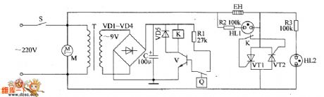
The eggs hatch incubator circuit is composed of the power supply circuit, temperature detection control circuit and indication circuit, and it is shown as the chart. Power supply circuit is composed of the power switch S, power transformer T, rectifier diodes VD1 ~ VD4 and filter capacitor C. Temperature detection control circuit is composed of electric hot thermometer Q, resistor R1, transistor V, Relay K, diode VD5, thyristors VT1, VT2 and fan motor M. Indicating circuit consists of resistors R2, R3 and neon lights HL1, HL2.
(View)
View full Circuit Diagram | Comments | Reading(1515)
Linear CMOS oscillator circuit
Published:2011/8/6 3:03:00 Author:nelly | Keyword: Linear, CMOS, oscillator
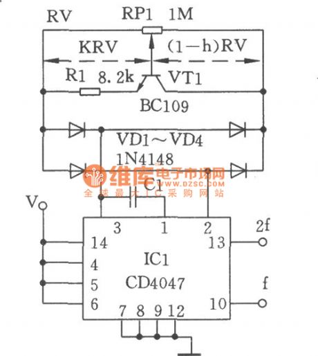
Figure shows the linear CMOS oscillator circuit. With the potentiometer RPl , the frequency of the CD4047 CMOS can be adjusted in the range of 1:100. When the transistor, which can be used as the variable resistor, is added, the adjustment circuit, which can have the linear relationship with the frequency, can be formed. The emitting resistor RI of VTI can set the current of IC with the variable base voltage. the electric bridge, which is formed by the diode VDl ~ VD4,is used to ensure the symmetry work both in negative and positive cycle.
(View)
View full Circuit Diagram | Comments | Reading(2073)
Eggs automatic incubator circuit diagram 3
Published:2011/8/5 2:21:00 Author:Ecco | Keyword: Eggs automatic incubator
The eggs automatic incubator circuit is composed of the power supply circuit, temperature / ventilation control circuit, automatic egg turning control circuit and temperature indication circuit, and it is shown in Figure 3. Power supply circuit is composed of the power switch S3, power transformer T, bridge rectifier UR and capacitors C2 ~ C4, current limiting resistor R12 and zener diode VS. R1 ~ R17 use 1/4W carbon film resistors or metal film resistors. RP1 ~ BP5 use high-quality synthetic membrane potentiometers or multi-turn potentiometers; RP6 uses the organic solid potentiometer. C1, C4 ~ C6 and C8 select monolithic capacitors.
(View)
View full Circuit Diagram | Comments | Reading(6067)
Temperature And Humidity, Liquid Level Multipurpose Automatic Controller Circuit
Published:2011/8/5 8:48:00 Author:Robert | Keyword: Temperature, Humidity, Liquid Level, Multipurpose, Automatic, Controller
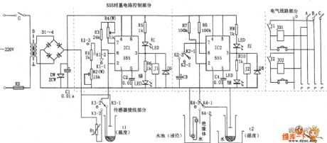
The picture shows the temperature and humidity, liquid level multipurpose automatic controller. This circuit is made up of buck rectifier filter power circuit, temperature and humidity sensor, frequency variable oscillator and single stable timing control circuit and so on. The sensor could use the thermistor, photoresistor, conductive mercury thermometer and other sensing elements. It could crossly connect the 555's charging and discharging loop circuit or the trigger port. So it would change the oscillator's frequency or 555's trigger status. When the predetermined temperature is higher than the environment temperature, the sensor's internal two mercury columns would be separate to be open circuit, so this make the IC1 reset because of the pin 2 staying in high voltage level. Then the pin 3 would output low voltage level to make the relay J1 have no action, as well as make the electrical heater's power conducted to heating. (View)
View full Circuit Diagram | Comments | Reading(2776)
Frequency modulation (FM) waveform generator circuit
Published:2011/8/6 2:22:00 Author:nelly | Keyword: Frequency modulation, waveform generator
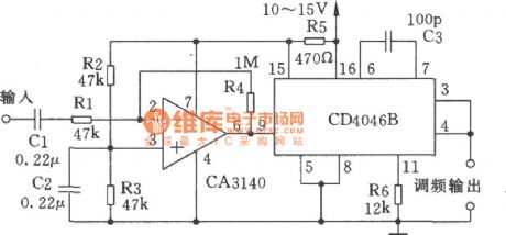
The figure shows the frequency modulation waveform generator circuit which can generate 220 kHz frequency. The regulator, which is inside the CD4068, can provide the stable supply voltage for the op-amp CA3140. The rated voltage is 5.4V, and R5 is the limiting resistor of regulator. (View)
View full Circuit Diagram | Comments | Reading(1789)
Electronic ERNIE Device Circuit
Published:2011/8/5 9:41:00 Author:Robert | Keyword: Electronic, ERNIE
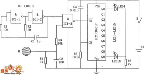
The picture shows the electronic ERNIE device's specific circuit. The IC1 is CD4011 with two input ports and four NAND gates. And the NAND gate IC1-1, IC1-2 make up the clock pulse generator, The NAND gate IC1-3 make up the counter gate circuit. Its one input port is connected with the clock pulses generator's output port and the other input port is connected to the touching metal sheet M through the resistor R3. The IC2 is decimal counter/divider CD4017. Its output ports Q0~Q9 have been added ten LED which are LED1~LED10. They are standing for 0~9 ten numbers separately. The capacitor C2 and the resistor R5 make up a electrifying automatical clearing and reset circuit. When the people's hand has not touched the metal sheet, the NAND gate IC1-3's lower input port is low voltage level, which make the counter gate closed and the IC2 would not count. (View)
View full Circuit Diagram | Comments | Reading(1259)
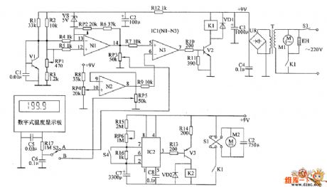
Eggs automatic incubator circuit diagram 2
Published:2011/8/5 2:17:00 Author:Ecco | Keyword: Eggs automatic incubator
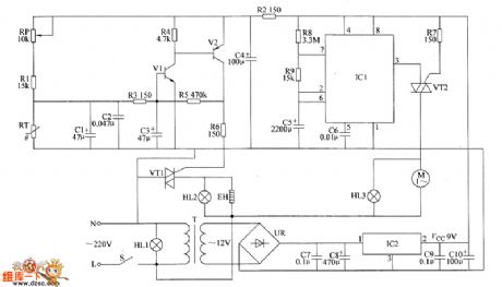
The eggs automatic incubator circuit is composed of the power supply circuit, temperature detection control circuit and eggs timing turning circuit, and it is shown as the chart. Power supply circuit is composed of the power switch S, power light HL1, power transformer T, bridge rectifier UR, filter capacitors C7 ~ CIO and three-terminal voltage regulator integrated circuit IC2. Temperature detection control circuit consists of resistors R1 ~ R6, capacitors C1 ~ C4, transistors V1, V2, thermistor RT, thyristor VT1, heating indicating lamp HL2 and heater EH. Eggs timing turning circuit is composed of the time-base integrated circuit IC1, resistors R7 ~ R9, capacitors C5, C6, thyristor VT2, motor M and eggs turning light HL3.
(View)
View full Circuit Diagram | Comments | Reading(3594)
Eggs automatic incubator circuit diagram 1
Published:2011/8/5 2:12:00 Author:Ecco | Keyword: Eggs automatic incubator
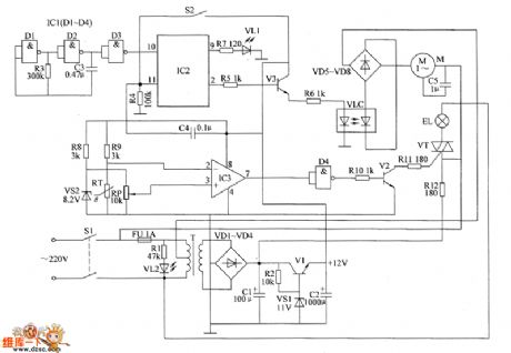
The eggs automatic incubator circuit is composed of the power supply circuit, automatic egg turning control circuit and temperature control circuit and other components, and it is shown the chart. Power supply circuit is composed of the power switch S1, fuse FU, the power transformer T, rectifier diodes VD1 ~ VD4, filter capacitors C1, C2, resistors R1, R2, power indicator LED VL2, voltage regulator VS1 and power regulator diode V1. Temperature control circuit is composed of the thermistor RT, voltage regulator diode VS2, potentiometer RP, resistors R8 ~ R12, operational amplifier integrated circuit IC3, IC1's internal NAND gate D4, transistor V2, thyristor VT and heating lighting lamp EL and other components.
(View)
View full Circuit Diagram | Comments | Reading(5868)
Keeping Recording Continuous Sound Control Circuit
Published:2011/8/5 19:01:00 Author:Robert | Keyword: Keeping, Recording, Continuous, Sound Control
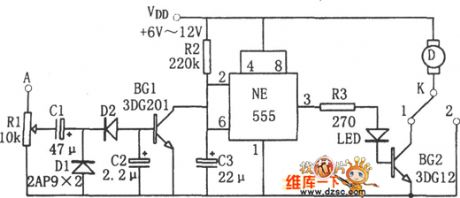
The picture shows the keeping recording continuous sound control circuit. This circuit's key point is the monostable delay circuit which is made up by 555 and R2, C3. The sound recording signal is added on the A port for input. When the A port has no sound recording signal input, the transistor BG1 would be not conducted to make the 555's pin 6 be high voltage level. So the 555 resets and output low voltage level on pin 3. And the BG2 is correspondingly not conducted and the motor is not working for recording. When the A port has sound recoding signal input, the D1, D2, C2 are processing for voltage doubler rectifier. And the BG1 is correspondingly saturated and conducted. The pin 2 would be in low voltage level (<1/3VDD) to make the 555 set. The pin 3 would output high voltage level so that the BG2 is also saturated and conducted. The motor D is electrified and then it is working for recording. (View)
View full Circuit Diagram | Comments | Reading(706)
SS0619 Touching stepping dimmer circuit diagram
Published:2011/8/5 2:33:00 Author:Ecco | Keyword: Touching stepping dimmer
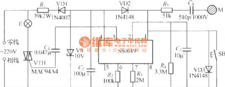
The touching stepping dimmer shown as the chart is composed of SS0619 IC, and it has touching and keying modes, which can make the brightness of E change optionally at the cycle of low, medium, bright, turning off .
(View)
View full Circuit Diagram | Comments | Reading(863)
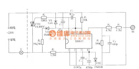
SS0614 Touching stepless dimmer circuit
Published:2011/8/5 2:38:00 Author:Ecco | Keyword: Touching stepless dimmer
The touching stepless dimmer shown as the chart is composed of SS0614 IC, and it uses two-wire system connection, which does not need to change the original wiring in the room. Touching M can make the voltage on the two ends of the lampbe adjustablein 27 ~200V.
(View)
View full Circuit Diagram | Comments | Reading(873)
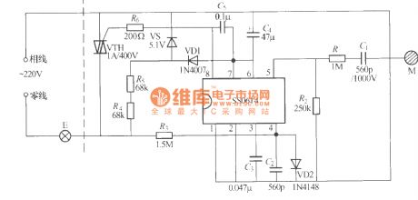
SS0613 Touching stepless dimmer circuit
Published:2011/8/5 2:35:00 Author:Ecco | Keyword: Touching stepless dimmer
The touching stepless dimmer shown as the chart is composed of SS0613 IC, and it uses two-wire system connection, which can directly replace ordinary switch to transform the ordinary light into touching stepless dimmer.
(View)
View full Circuit Diagram | Comments | Reading(1354)
Pulse position modulator (555) circuit
Published:2011/8/6 8:05:00 Author:nelly | Keyword: Pulse position, modulator
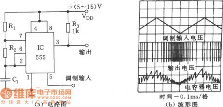
(a) circuit diagram (b)waveform (View)
View full Circuit Diagram | Comments | Reading(2355)
Single-junction transistor sine wave oscillator circuit
Published:2011/8/7 1:30:00 Author:nelly | Keyword: Single-junction, transistor, sine wave, oscillator
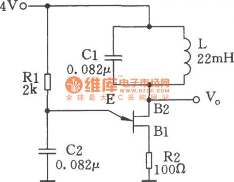
The single-junction transistor is always used in the sawtooth generator and pulse generator, and it also can form the simple sine wave generation circuit. As an oscillator circuit of the discrete component, it uses fewest components. As the figure shown, compared with the simple single-junction tube remittent oscillator circuit, this circuit adds a LC tuned circuit at the second base. By the excitation of the single-junction tube current pulse, the tuned circuit generates sine wave oscillation. Tuned resistor R1 can control the size of current pulse and have the sine wave at B2.
(View)
View full Circuit Diagram | Comments | Reading(4057)
Fire-Fighting Emergency Light Circuit
Published:2011/8/5 21:15:00 Author:Robert | Keyword: Fire-Fighting, Emergency, Light
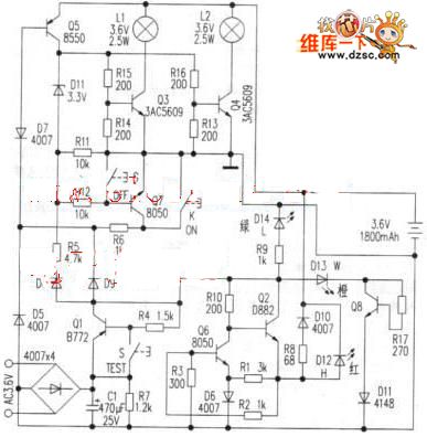
1. The battery charging circuit external power would charge for the battery with constant current through the Q2, Q6, R8, D10. When there is the external power supply, the charging current would charge the battery trough R8, D10 and also the charging indication lamp D12 would light.The picture shows the fire-fighting emergency light circuit.2.The light control circuit is made up of Q3, Q5, Q7 and key K, G. When there is no commercial power, by pressing the key K (openning), the Q5 would be saturated and conducted. The Q5's collector polar current would maintain the Q7 to keep conducted through R12. The D11 reverse breakdown is working in stable mode. The Q5's collector polar voltage would provide the bias voltage for the Q3, Q4 to make they conducted to light the L1 and L2. When pressing the key G (closing), the Q7 would be closed which remove the conducted conditions of Q5, and the lamp would be off. (View)
View full Circuit Diagram | Comments | Reading(2592)
Quartz crystal sine wave oscillator circuit
Published:2011/8/7 1:42:00 Author:nelly | Keyword: Quartz crystal, sine wave, oscillator
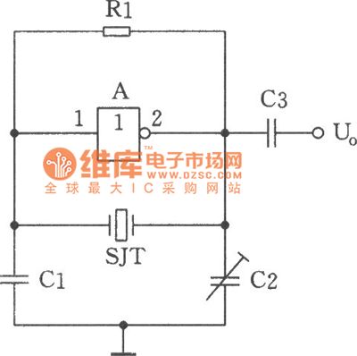
The picture shows the sine wave oscillator which is composed of the quartz crystal SJT and the gate A of the hex inverter IC CD4069.Compared with the ordinary RC phase-shift oscillator, the stability of crystal oscillator’s frequency can reach 10-5 or higher. This high index (The stability of the RC phase-shift oscillator’s frequency only can reach 10-2) can not be reached by the RC phase-shift oscillator. CMOS NAND gate and the negative feedback bias resistor R1 form the inverting amplifier circuit. Quartz crystal SJT, C1 and C1 form the 7c type positive feedback branch.
(View)
View full Circuit Diagram | Comments | Reading(2132)
The wideband voltage controlled oscillator circuit composed of CD4046
Published:2011/8/6 2:35:00 Author:nelly | Keyword: wideband, voltage controlled, oscillator
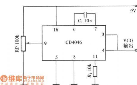
The wideband voltage controlled oscillator circuit composed of CD4046 is as shown: (View)
View full Circuit Diagram | Comments | Reading(4201)
The voltage controlled oscillator circuit composed of CD4007
Published:2011/8/6 2:44:00 Author:nelly | Keyword: voltage controlled, oscillator
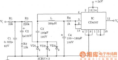
The voltage controlled oscillator is as shown. Through the low-pass filter Rl ~ R3, Cl~C2, this voltage controlled signal provides the varactor diode VDl ~ VD3 with DC voltage which will change with the frequency and phase. The output of the voltage controlled oscillator is composed of the inductor L, capacitor C3, C4 and varactor diode VDl ~ VD3 and integrated circuit IC (CD4007). (View)
View full Circuit Diagram | Comments | Reading(3533)
| Pages:592/2234 At 20581582583584585586587588589590591592593594595596597598599600Under 20 |
Circuit Categories
power supply circuit
Amplifier Circuit
Basic Circuit
LED and Light Circuit
Sensor Circuit
Signal Processing
Electrical Equipment Circuit
Control Circuit
Remote Control Circuit
A/D-D/A Converter Circuit
Audio Circuit
Measuring and Test Circuit
Communication Circuit
Computer-Related Circuit
555 Circuit
Automotive Circuit
Repairing Circuit