
Circuit Diagram
Index 598
AC_LINE_MONITOR
Published:2009/7/14 22:33:00 Author:Jessie
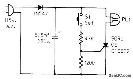
Detects AC line failures of any duration and turns off neon lamp PL1 to indicate that clocks require resetting. Circuit is plugged into AC outlet, and S1 is pushed to trigger SCR on and send current through lamp.-J. R. Nelson, Some Ideas for Monitoring A.C. Power Lines, CQ, July 1973, p 56. (View)
View full Circuit Diagram | Comments | Reading(1173)
POSITIVE_PEAK_DETECTOR
Published:2009/7/14 21:33:00 Author:May
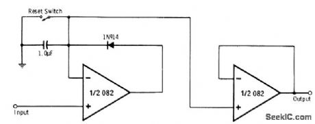
Circuit responds to and remembers peak positive excursions of input signal over period of time with first half of 082 dual opamp. Other half of opamp serves as voltage follower for isolating peak detector from output. Memory time is typically several minutes, depending on rate at which capacitor discharges due to its own leakage current, diode leakage current, opamp bias currents, and slight loading effect of voltage follower. Closing reset switch momentarily discharges capacitor in readiness for storing new peak value.-R. Melen and H. Garland, Understanding IC Operational Amplifiers, Howard W. Sams, Indianapolis, IN, 2nd Ed., 1978, p 96-97.
(View)
View full Circuit Diagram | Comments | Reading(0)
RELAY_DELAY
Published:2009/7/14 22:33:00 Author:Jessie
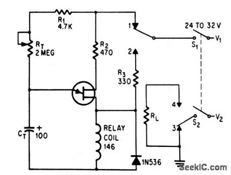
Uuijunction transistor is used to delay operation of relay from 0.5 sec to 3 minutes. CT-RT determine delay interval.-D. V. Jones, Quick-On-The-Trigger Design, Electronics, 38:12, p 105-110. (View)
View full Circuit Diagram | Comments | Reading(923)
OUT_OF_LIMIT_VOLTAGE_SENSOR
Published:2009/7/14 21:31:00 Author:May
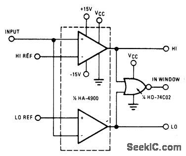
High switching speed, low offset current, and low offset voltage of Harris HA-4900/4905 precision quad comparator make circuit well suited for industrial process control applications requiring fast, accurate decision-making based on voltage levels. Outputs can be used to drive alarm indicator or initiate corrective action.- Linear & Data Acquisition Products, Harris Semiconductor, Melbourne, FL, Vol. 1, 1977, p 2-96. (View)
View full Circuit Diagram | Comments | Reading(1165)
VIDEO_OPERATED_CONTROLLER
Published:2009/7/14 22:33:00 Author:Jessie
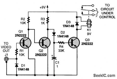
If you need a timer that is programmable, precise, and will provide long delays, almost any VCR can be used without any internal modification. All that is required is a circuit that will detect the presence of the video output signal when the recorder turns on. The first diode (D1) clamps the negative video to ground. The rest of the circuit responds to the frame markers to charge up the capacitor and turn on the relay. A tape isn't even required (in most cases) if the recorder is tuned to an active channel because the video-out signal appears as soon as the recorder is turned on. Therefore, the circuit's ON time is not limited by tape length. (View)
View full Circuit Diagram | Comments | Reading(908)
VCO_SENSES_VOLTAGE_LIMITS
Published:2009/7/14 21:30:00 Author:May
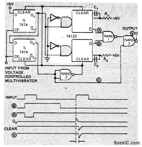
Used to indicate when pulse voltage goes outside preset limits for pulse period. Output pulse rate of voltage-controlled MVBR is monitored to implement double-ended limit detector consisting of 2-bit shift register, two monos, inverter, and two NAND gates. Circuit compares period of input pulses to preset maximum and minimum limits. Output at Y goes low whenever input pulse rate is outside limits, which are deter-mined by R1C1 and R2C2 time constants.-B. Brandstedt, Double-Ended Limit Detector Senses Voltage with VCO, EDN Magazine, Nov. 15, 1972, p 47-48. (View)
View full Circuit Diagram | Comments | Reading(1024)
LED_VOLTAGE_MONITOR
Published:2009/7/14 21:29:00 Author:May
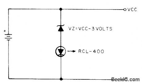
Uses Litronix RCL400 current-controlled LED having built-in voltage-sensing IC that turns on LED at 3 V and turns it off at 2 V. Use suitable zener or string of forward-biased silicon diodes to make VZ equal to 3 V less that VCC. Thus, for 4.5-V battery, put two silicon diodes in series with LED to make VZ 1.5 V across them.-S, W. Hawk-inson, A Battery Voltage Monitor, 73 Magazine, July 1977, p 52.
(View)
View full Circuit Diagram | Comments | Reading(1002)
SIMPLE_VIDEO_RECEIVER
Published:2009/7/14 21:28:00 Author:May
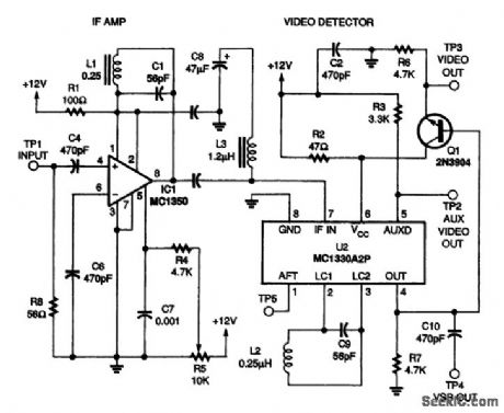
The IF input from the tuner is fed into an MC1350 amplifier (IC1) through capacitor C4. The 56Ω input resistor R8 approximates the impedance of the tuner's 50-Ω output. The IF amplifier is tuned by variable inductor L1 and capacitor C1, and its gain is controlled by potentiometer R5. The output of the IF amplifier is coupled into an MCl330 low-level video detector (IC2) through C5. The optional LC trap circuit, consisting of C8 and L3, can be adjusted to eliminate a specific signal, but the circuit will work well without the trap. The MC1330 is also tuned with a tank circuit, consisting of L2 and C9. The video outputs are biased with resistor networks. The noninverted video is fed into the base of a 2N3904 NPN transistor Q1 configured as a unity-gain, common-collector, buffer amplifier for impedance matching. The primary video output is taken from the top of Q1's emitter resistor R6, and the auxiliary video output is taken from pin 5 of IC2. The VSB output is an ac-coupled version of the primary output, and it can be used for any sound output you wish to use in the future, The switching carrier output can be used for automatic fine-tuning (AFT) circuits. (View)
View full Circuit Diagram | Comments | Reading(5063)
DIVIDE_BY_5_RING_COUNTER
Published:2009/7/14 21:28:00 Author:May
Each stage acts as nonsaturating current-mode switch. Two identical counters are cascaded in uhf prescaler of frequency synthesizer for military uhf transceiver .-L. F. Blachowicz , Dial any Channel to 500 Mhz, Electronics, 39:9, p 60-69. (View)
View full Circuit Diagram | Comments | Reading(1110)
SCALE_OF_TEN_DIVIDER
Published:2009/7/14 21:27:00 Author:May
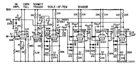
Consists of four cascaded Eccles-Jordan binary dividers with feedback loops, to recycle at 10. Operates up to 500 kc.-J. K. Goodwin, Digital Tachometer Aids in Turbine Design, Electronics, 32:15, p 58-61. (View)
View full Circuit Diagram | Comments | Reading(1177)
FOUR_NUMBER_CALLER
Published:2009/7/14 21:26:00 Author:May
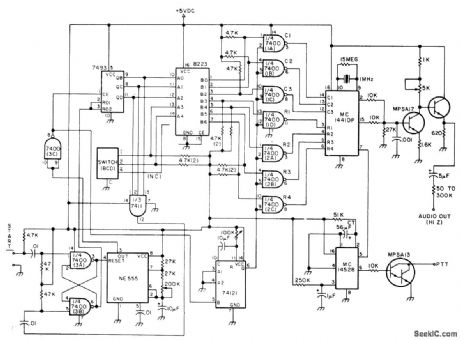
Motorola MC14410 CMOS Touch-Tone generator chip forms basis for automatic dialer using BCD thumbwheel switch to choose telephone number desired.Numbers are stored in 256-bit PR0M by conventional programming. Article shows how auto patch access and disconnect switches are added. To make telephone call from car through repeater, select number desired, push access button and, when dial tone is heard, push start button to transmit tones corresponding to de-sired number. Article covers circuit operation, programming, and coding, and gives additional circuit using 512-bit PR0M to provide eight telephone numbers.-W. J. Hosking, Drive More Safely with a Mobile Dialer, 73 Magazine, Feb. 1977, p 102-104. (View)
View full Circuit Diagram | Comments | Reading(1941)
JK_FLIP_FLOP
Published:2009/7/14 21:26:00 Author:May
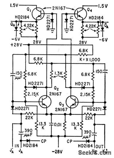
Consists of transistorized Eccles-Jordan switch, with collectors damped with diodes to stabilize operating points. Used to provide current for driving gating circuits of voltage amplifiers for magnetic memory drum.-A. J. Strassman and R. E. Keeter, Clock Track Recorder For Memory Drum, Electronics, 32:41, p 74-76. (View)
View full Circuit Diagram | Comments | Reading(983)
RTTY_SPEED_CONVERTER
Published:2009/7/14 22:45:00 Author:Jessie
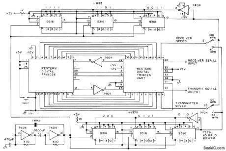
Digital speed converter for amateur RTTY permits transmitting either above or below input speed from key-board or tape Uses FR1502E 40-character 9-bitFIFO storage chip, TR1602A universal asynchronous receiver-transmitter, and six Fairchild 9316 programmable dividers. Values shown give choice of 60 or 100 WPM for receiving and for transmitting, derived by dividing down from same 1-MHz clock. Input and output are TTL-compatible.-A. Sperduti, The 60 WPM Conversion, 73 Magazine, April 1977, p 158-159. (View)
View full Circuit Diagram | Comments | Reading(1308)
MULTICHANNEL_ALARM
Published:2009/7/14 21:25:00 Author:May
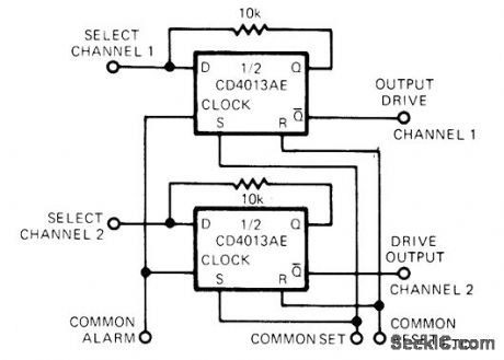
Half of CD4013AE flip-flop serves as latching AND gate in each channel being monitored for vervoltage, overtemperature, or any other out-of-tolerance condition that can be represented by logic 1 level applied to terminal that connects to clock inputs of all flip-flops. Any number of additional channels can be paralleled to Gammon terminals. Each channel has own transistor driver and either LED or audio alarm. Alarm condition is held until operator resets system by applying voltage to common set terminal. Article shows how to obtain additional flexibility by adding NAND and AND gates to each select input and to common alarm input.-J. C. Nichols, CM0S D Flop Makes Latching AND Gate, EDN Magazine, April20, 1974, p 89 and 91. (View)
View full Circuit Diagram | Comments | Reading(1155)
STABLE_AUDIO_AMPLIFIER
Published:2009/7/14 22:44:00 Author:Jessie
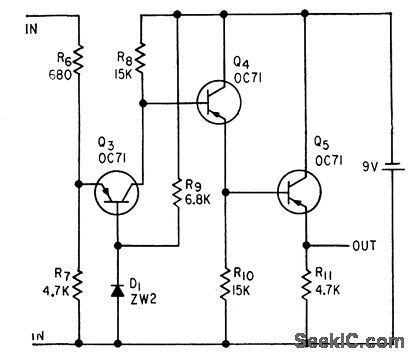
Provides low input and output impedances, along with stable gain for wide range of transistor parameters and thus for temperature and supply voltage variations, as required for sound level meter.-W. V. Richings and B. J.White, Transistorized Sound Level Meter, Electronics, 33:25, p 64-66. (View)
View full Circuit Diagram | Comments | Reading(979)
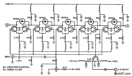
SIX_STEP_RING_DELAY
Published:2009/7/14 22:44:00 Author:Jessie
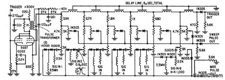
When double-triode blocking oscillator is fired by input trigger, it delivers 0.6-microsec pulse into 1-microsec delay line which, in turn, delivers pulse to next delay line. After sixth delay, pulse is used as trigger for next ring unit.-M. T. Nadir, Microsecond Sampler Handles 126 Channels, Electronics, 32:4, p 36-39. (View)
View full Circuit Diagram | Comments | Reading(1372)
PREAMPLIFIER_FOR_DYNAMIC_PICKUP
Published:2009/7/14 22:43:00 Author:Jessie

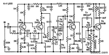
Accepts signal from variable-reluctance cartridge.Includes RIAA frequency-correcting network, variable bass and treble compensation,volume control, and loudness control that attenuates midfrequencies as loudnesslevel is decreased, to emphasize lows and highs during soft musical passages.-R.Minton,Designing High-Quality A-F Transistor Amplifiers, Electronics, 32:24, p 60-61. (View)
View full Circuit Diagram | Comments | Reading(2406)
OVERVOLTAGE_ALARM
Published:2009/7/14 21:24:00 Author:May
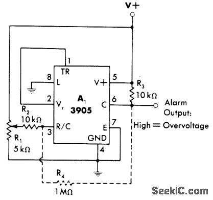
Connection shown for 3905 timer makes output go high for energizing suitable alarm when supply voltage rises above predetermined level. Timer is connected as noninverting comparator that compares its fixed voltage-comparison threshold of 2 V with fraction of supply voltage determined by setting of R1. Optional resistor R4 can be added if some hysteresis is desirable to prevent tripping of alarm by momentary fluctuations of supply.-W. G. Jung, IC Timer Cookbook, Howard W, Sams, Indianapolis, IN, 1977, p 230-231. (View)
View full Circuit Diagram | Comments | Reading(975)
MICROPOWER_VOLTAGE_TO_FREQUENCY_CONVERTER
Published:2009/7/14 22:43:00 Author:Jessie
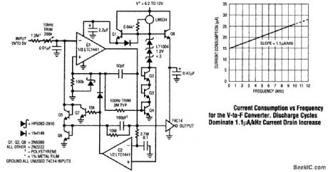
This voltage-to-frequency converter takes full advantage of the LTC1441's low power consumption under dynamic conditions. A 0- to 5-V input produces a 0- to 10-kHz output with 0.02 percent linearity, 60 ppm/°C drift, and 40 ppm/V supply rejection. Maximum current consumption is only 26μA, 100 times lower than that of currently available circuits. C1 switches a charge pump, composed of Q5, Q6, and the 100-pF capacitor, to maintain its negative input at 0 V. The LT1004s and associated components form a temperature- compensated reference for the charge pump. The 100-pF capacitor charges to a fixed voltage; hence, the repetition rate is the circuit's only degree of freedom to maintain feedback. Comparator C1 pumps uniform packets of charge to its negative input at a repetition rate precisely proportional to the input voltage-derived current.This action ensures that circuit output frequency is strictly and solely determined by the input volt-age. Start-up or input overdrive can cause the circuit's ac-coupled feedback to latch. If this occurs, C1's output goes low; C2, detecting this via the 2.7-MΩ/0.1-μF lag, goes high. This lifts C1's positive input and grounds the negative input with Q7, initiating normal circuit action. (View)
View full Circuit Diagram | Comments | Reading(1598)
LOW_COST_DISCRIMINATOR
Published:2009/7/14 22:41:00 Author:Jessie


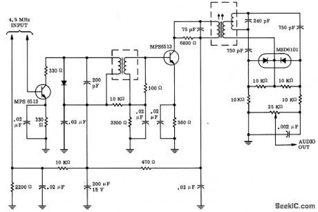
Uses two detectors fed 90° out of phase. Signals are demodulated conventionally for each phase, and the sum of the two signals is token across the whole output. Provides excellent operation as discriminator in 4.5.Mc tv sound detector.-J. B. Compton, A Low-Cost All Solid-Stale FM Discriminator for Consumer Applications, Motorola Application Note AN-212, Jan. 1966.
(View)
View full Circuit Diagram | Comments | Reading(994)
| Pages:598/2234 At 20581582583584585586587588589590591592593594595596597598599600Under 20 |
Circuit Categories
power supply circuit
Amplifier Circuit
Basic Circuit
LED and Light Circuit
Sensor Circuit
Signal Processing
Electrical Equipment Circuit
Control Circuit
Remote Control Circuit
A/D-D/A Converter Circuit
Audio Circuit
Measuring and Test Circuit
Communication Circuit
Computer-Related Circuit
555 Circuit
Automotive Circuit
Repairing Circuit