
Circuit Diagram
Index 72
Batteries charger & PSU
Published:2013/7/18 20:34:00 Author:muriel | Keyword: Batteries charger & PSU
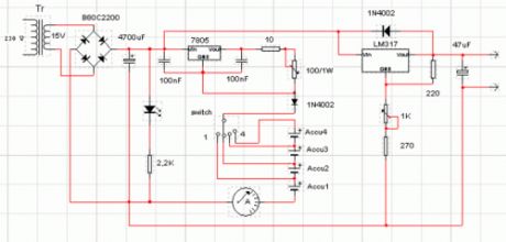
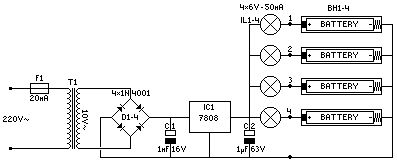
This circuit was created for digital cameras. It's known the digital cameras have considerable power consumption. For example my camera Minolta E223 requires approximately 800 mA. In practice a mains power supply or high capacity NiMH accumulators (batteries) can satisfy this demand.
This circuit consists of two parts, charger and adapter. The transformer, rectifier bridge and buffer condensator are common. Adapter is quite simply its main part is an adjustable voltage regulator LM 317 according to usual setting. Output is a suitable for camera jack plug. Voltage can be adjusted in range 2-9 V.In the charger circuit a 7805 fixed voltage regulator works as current generator assured constant current during charging. This charging current can be adjusted with the 100 /1W potentiometer in range about 50-300 mA indicated by a small current measuring instrument. From one to four batteries can be charged simultaneously. The switch must be set according to number of batteries, and charging current of batteries given by manufacturer must be adjusted. This circuit doesn't measure charging time and charging condition of batteries. Manufacturers give charging time, usually 14-16 h. I solved this problem with a simply, cheap mechanical mains timer. I think its accuracy is sufficient.
(View)
View full Circuit Diagram | Comments | Reading(1169)
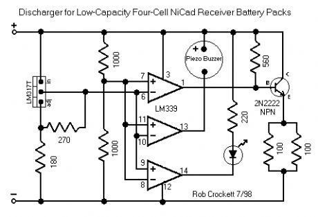
Discharger for Receiver Battery Packs
Published:2013/7/18 20:33:00 Author:muriel | Keyword: Discharger , Receiver, Battery Packs
View full Circuit Diagram | Comments | Reading(993)
Low Voltage Alarm circuit
Published:2013/7/18 20:32:00 Author:muriel | Keyword: Low Voltage, Alarm circuit
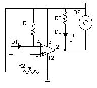
This low voltage circuit can be used to monitor batteries and other volatile sources of current for problems. The circuit sounds an alarm and lights an LED, but can be interfaced to any number of other circuits for many different uses. (View)
View full Circuit Diagram | Comments | Reading(1236)
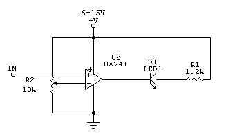
Voltage Monitor
Published:2013/7/18 20:31:00 Author:muriel | Keyword: Voltage Monitor
View full Circuit Diagram | Comments | Reading(0)
Receiver Battery Low Voltage Alarm
Published:2013/7/18 20:31:00 Author:muriel | Keyword: Receiver, Battery, Low Voltage, Alarm
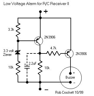
Here is another equally cool low voltage alarm circuit for your glider receiver battery that I've shamelessly stolen from George Steiner's book A to Z--Radio Control Electronic Journal (see below). I've modified it to use with small battery packs in R/C gliders. This design has a trigger voltage at about 4.3 volts, and it draws 1mA or less when quiet and about 4mA when buzzing. This can be constructed from parts fromt Radio Shack, though you may need to order a few through them.The voltage of a receiver system is punctuated by low-voltage spikes every time the servo motors spin up, since the servos draw more than the battery can deliver. With large receiver battery packs, this is not as much of an issue, and it may not be noticeable. However with 270mA and smaller battery packs, particularly with more than two servos, low voltage alarms can chirp constantly, every time a servo moves. The challenge is to design in a little slack or delay, just enough so that you are not annoyed by constant chirping, but not too much so that the chirps can give you a warning before the battery is completely exhausted. Here, this hysteresis is adjusted with the capacitor. For large packs (600mA and above), no capacitor is probably needed, although I've been using a 1uF capacitor on my open class ship with 6 servos and a 600mA battery. For 270 mA and two servos, I'd suggest trying a 1uF capacitor. For 150mA or less, a 2.2uF capacitor works well. If you want to know only when the battery has finally reached the trigger voltage, try a 5uF (or 4.7uF) capacitor. The actual type of capacitor is not critical, but tantalum capacitors are physically smaller. If you want to worry about the polarity of the capacitor, the negative side should be directed toward the negative pole of the battery, but at these relatively low voltages compared to the capacitor rating, the polarity probably does not matter.This circuit is set up for a four cell receiver battery pack at a trigger voltage of about 4.3 volts (about 1.1volts/cell). You can adjust R1 (here a 3.3k resistor) to change the trigger voltage of the circuit. For example, for a 5 cell pack, to change the trigger voltage to 5.5 volts, change R1 to 2.2k. For a three cell pack, to change the trigger voltage to 3.3 volts, change R1 to 6.8 k (or use two 3.3k resistors in parallel by soldering a resistor in each hole and twisting together the top leads). Because of slight variability in tolerances of the componants, you should check this little device with a variable power source and a voltmeter to confirm its trigger point. Alternately, use your digital voltmeter or expanded scale voltmeter to calibrate its chirp pattern by measuring the voltage of the onboard battery pack intermittently as you fly.Make sure the band on the Zener diode is toward the + side (toward R1). Solder a battery connector or servo connector to the board with positive and negative as shown, and plug the connector into an unused slot in your receiver. (View)
View full Circuit Diagram | Comments | Reading(1593)
High And Low Voltage Cut Off With Time Delay 6
Published:2013/7/18 20:29:00 Author:muriel | Keyword: High And Low Voltage , Cut Off, Time Delay
View full Circuit Diagram | Comments | Reading(1285)
High And Low Voltage Cut Off With Time Delay 5
Published:2013/7/18 20:28:00 Author:muriel | Keyword: High And Low Voltage, Cut Off , Time Delay
View full Circuit Diagram | Comments | Reading(1498)
High And Low Voltage Cut Off With Time Delay 4
Published:2013/7/18 20:27:00 Author:muriel | Keyword: High And Low Voltage, Cut Off, Time Delay
View full Circuit Diagram | Comments | Reading(1098)
High And Low Voltage Cut Off With Time Delay 3
Published:2013/7/18 20:27:00 Author:muriel | Keyword: High And Low Voltage, Cut Off, Time Delay
View full Circuit Diagram | Comments | Reading(1312)
High And Low Voltage Cut Off With Time Delay 2
Published:2013/7/18 20:26:00 Author:muriel | Keyword: High And Low Voltage , Cut Off , Time Delay

View full Circuit Diagram | Comments | Reading(1109)
High And Low Voltage Cut Off With Time Delay
Published:2013/7/17 22:06:00 Author:muriel | Keyword: High And Low Voltage , Cut Off, Time Delay
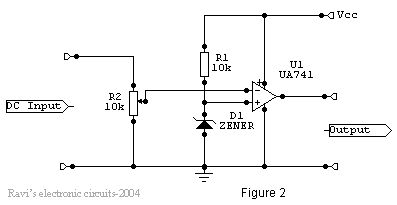
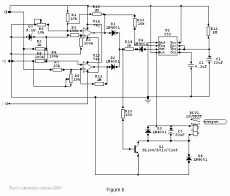
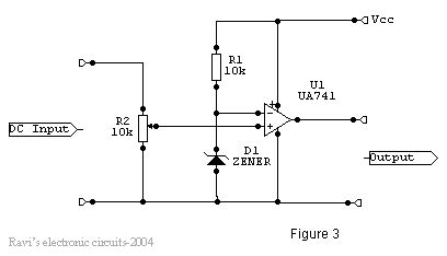
OverviewThe power line fluctuations and cut-offs cause damages to electrical appliances connected to the line. It is more serious in the case of domestic appliances like fridge and air conditioners. If a fridge is operated on low voltage, excessive current flows through the motor, which heats up, and get damaged.The under/over voltage protection circuit with time delay presented here is a low cost and reliable circuit for protecting such equipments from damages. Whenever the power line is switched on it gets connected to the appliance only after a delay of a fixed time. If there is hi/low fluctuations beyond sets limits the appliance get disconnected. The system tries to connect the power back after the specific time delay, the delay being counted from the time of disconnection. If the power down time (time for which the voltage is beyond limits) is less than the delay time, the power resumes after the delay: If it is equal or more, then the power resumes directly.This circuit has been designed, built and evaluated by me to use as a protector for my home refrigerator. This is designed around readily available semi-conductor devices such as standard bipolar medium power NPN transistor (D313/SL100/C1061), an 8-pin type 741 op-amp and NE555 timer IC. Its salient feature is that no relay hunting is employed. This draw back is commonly found in the proctors available in the market.The complete circuit is consisting of various stages. They are: - Dual rail power supply, Reference voltage source, Voltage comparators for hi/low cut offs, Time delay stage and Relay driver stage. Lets now look at the step-by-step design details.
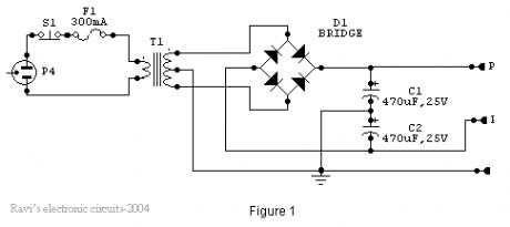
Dual rail power supply.This is a conventional type of power supply as shown in Figure 1. The power is applied through the step-down transformer (230/12-0-12V/500mA). The DC proportional to the charging input voltage is obtained from bridge rectifier. Two electrolytics are there to bypass any spikes present. Bridge is capable of handling currents up to 1 Amp.Output is given by: -V(out) = 0.71 X V (secondary)= 0.71 X 24V= 17.04 V(This equation is similar for the negative rail as well)
(View)
View full Circuit Diagram | Comments | Reading(1451)
Nicad Battery Charger 2
Published:2013/7/17 22:01:00 Author:muriel | Keyword: Nicad Battery Charger
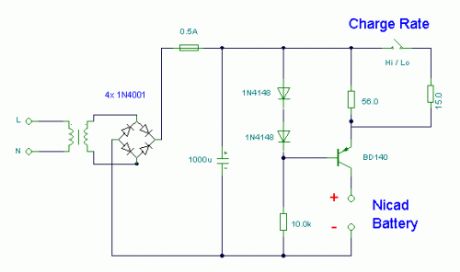
Notes:This simple charger uses a single transistor as a constant current source. The voltage across the pair of 1N4148 diodes biases the base of the BD140 medium power transistor. The base - emitter voltage of the transistor and the forward voltage drop across the diodes are relatively stable. The charging current is approximately 15mA or 45mA with the switch closed. This suits most 1.5V and 9V rechargeable batteries. The transformer should have a secondary rating of 12V ac at 0.5amp, the primary should be 220/240volts for Europe or 120volts ac for North America. (View)
View full Circuit Diagram | Comments | Reading(1268)
Ni -Cd Batteries Charger
Published:2013/7/17 22:00:00 Author:muriel | Keyword: Ni -Cd Batteries Charger
View full Circuit Diagram | Comments | Reading(1153)
Precision Receiver Battery Low Voltage Alarm
Published:2013/7/17 21:59:00 Author:muriel | Keyword: Precision , Receiver, Battery, Low Voltage, Alarm
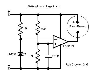
Flying hand launch gliders means living with small capacity receiver NiCad battery packs. These small packs are light, but have the distinct disadvantage of rapidly depleting. You can carefully time your flights, but you end up either crashing when your plane seizes or using only a portion of the already small capacity of the battery. If you charge the battery in a slightly suboptimal fashion, your plane dies and bites the dirt (done that, crashed). This devices will allow you to use a small mA pack and use the full capacity of your battery.This device of my design uses seven componants on a single side PC board. With a 6 inch connector, the whole thing weighs about 0.2 oz. The alarm sounds with a voltage at or below 4.5v, and the circuit draws 2.4-2.7 mA when quiet and 5.6mA with the alarm (in my Hitec system, a receiver and two servos draw an average 75-100mA when flying). The LM336 and 3k resistor provide a precision reference 2.5 volts, and the two other resistors are a voltage divider that provide the sample voltage. The LM311 is a voltage comparator, and powers the buzzer when the sample voltage crosses the reference. Since servos draw current abruptly and intermittantly, the ambient battery voltage is puncuated by a series of low voltage spikes. The capacitor (not in the original design in the picture) smooths these spikes somewhat so that the alarm does not chirp with every servo motion. These inverted voltage spikes are not so pronounced with larger capacity batteries; the capacitor may not always be be needed. While it is possible to smooth the voltage completely, this chirping provides a continuous and early indication of battery voltage. With the circuit here, the alarm chirps while slewing both servos of a reciever/two servo system when a 150mA battery is about half discharged, chirps with any servo motion when near completely discharged, and alarms continuously with about 5 minutes of flying time left. With a larger capacity battery, the sequence occurrs much nearer to complete discharge--perhaps no capacitor or a smaller one (say 1uf or 0.1uf) would do--and initial comparison with your measured voltages would be important to calibrate to your system. You can adjust the divider resistors for a higher or lower voltage alarm: Vout=Vin(R2/(R1+R2)) where Vout=2.5v and Vin is your selected alarm voltage, and R1 is the positive side and R2 is the negative side. Note that the LM336 has three pins and you only use two (break off the third). Solder a battery or servo connector to the board with positive and negative as shown, and plug the connector into an unused slot in your receiver. (View)
View full Circuit Diagram | Comments | Reading(1866)
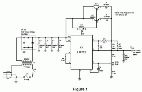
10 Amp 13.8 Volt Power Supply
Published:2013/7/17 21:58:00 Author:muriel | Keyword: 10 Amp , 13.8 Volt, Power Supply
View full Circuit Diagram | Comments | Reading(1493)
0-50V 2A Bench power supply
Published:2013/7/17 21:57:00 Author:muriel | Keyword: 0-50V , 2A, Bench power supply
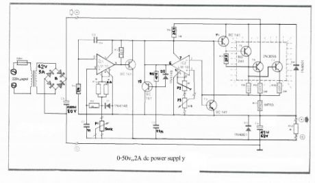
I use the lm10 IC because it has a reference voltage and that’s useful for dc power supply. With two ICs can take different output voltage and amperage. This circuit is protected from short circuit.P2 is for controlling the current at the range of 0-2A. Stabilize the output voltage with R4 on negative pin on op-amp and with R2 & P1 on positive pin.
Op-amp output controls T1 that not let ripple of voltage.T1 increase or decrease ampere of R6 and control the voltage of T5 & T4. Pin 1 is the reference voltage and reference voltage is losing some voltage on R1 that has 100uA . This current passes through P1 too.Vlose p1=100uA*Rp1This lose voltage regulate output voltage rate of output current is compare between reference voltage of P3 and lose voltage on R11.T3 is protecting short circuit with R11. For reduce out put voltage to 0v should parallel one resistor 470 ohm in out put. Minimum voltage is 0.4v. The maximum output voltage is fixed with R1b and should not become over of 50v. Therefore your transformer should give 36V, 3A with 4700uF capacitor. T6, T5, T7 need heatsilk. (View)
View full Circuit Diagram | Comments | Reading(1603)
LM317 VARIABLE POWER SUPPLY
Published:2013/7/17 21:56:00 Author:muriel | Keyword: LM317 , VARIABLE POWER SUPPLY
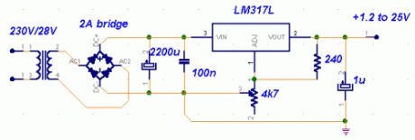
A truly timeless circuit. LM317 is a versatile and highly efficient 1.2-37V voltage regulator that can provide up to 1.5A of current with a large heat sink. It's ideal for just about any application. This was my first workbench power supply and I still use it.Since LM317 is protected against short-circuit, no fuse is necessary. Thanks to automatic thermal shutdown, it will turn off if heating excessively. All in all, a very powerful (and affordable!) package, indeed.Although LM317 is capable of delivering up to 37V, the circuit pictured here is limited to 25V for the sake of safety and simplicity. Any higher output voltage would require additional components and a larger heat sink.Make sure that the input voltage is at least a couple of Volts higher than the desired output. It's ok to use a trimmer if you're building a fixed-voltage supply.
Possible uses:Variable workbench power supply, fixed-voltage supply... Just about any possible application when no more than 1.5A is necessary.
(View)
View full Circuit Diagram | Comments | Reading(1290)
12 Volt 30 Amp PSU 2
Published:2013/7/17 21:55:00 Author:muriel | Keyword: 12 Volt, 30 Amp , PSU
View full Circuit Diagram | Comments | Reading(1225)
12 Volt 30 Amp PSU
Published:2013/7/17 21:54:00 Author:muriel | Keyword: 12 Volt, 30 Amp, PSU
View full Circuit Diagram | Comments | Reading(1186)
Flyback Transformer Driver
Published:2013/7/17 21:54:00 Author:muriel | Keyword: Flyback Transformer Driver
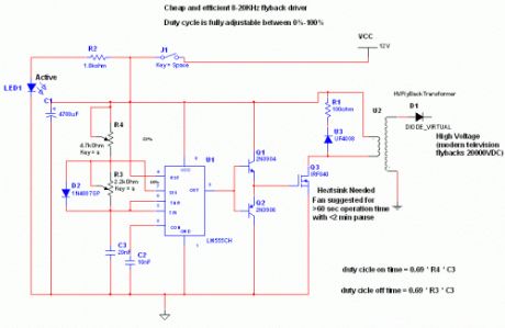
This is an efficient flyback driver for modern cylindrical rectified television flybacks. Many sites doesn't provide circuits driving these transformers, they simply say that they are bad.I don't agree. In fact I built this circuit. I spent a lot of time for finding resonant frequency (around 15Khz) and duty cycle. These transformers best work at around 90% duty cycle. You may notice corona breakdown at terminals and pfffff sound (as well as the ozone smell) when adjusting the off time trimmer to near 500-300 ohms. Of course it will work for other tipes of flyback as frequency and duty cycle have a large range.Frequency range can be increased using multiposition switch for other values of C3 capacitor ,for example 2 nF for 80KHz-200000KHz, but didn't found flybacks with so high resonant frequencies, in addition with higher values of c3 , eg 200nF, 2uF thefrequency will drop making possible the use of ignition coils, and rectified power transformers @50Hz to charge high voltage electrolitic caps at 300-400V). Unfortunately my ignition coil died because insulation breakdown (too long drawn arcs)...I was able to power a small (20cm) Spark Gap tesla coil Using these dc rectified flybacks to charge primary tank capacitor.
The operation is simpleThe 555 is wired as an astable and the capacitor is charged only through the 4,7Kohm trimmer (notice the diode) and discharged only through the 2.2 Kohm trimmer, making the duty cycle full adjustable. The square wave is then feed in a totem pole made up of a 2N3904 and a 2N3906, which are cheap, and easy to find. The totem pole ensures the gate being charged and discharged very fast (approx 50nS i think). The IRF840 is a cheap (i found it for 4euros) reliable and powerful power mosfet, it has current capability of 8 A continuous and 32A pulse, 800V drain source voltage, protecting internal zener diode. There is a snubbing network to ensure that voltage spikes are kept low (unless the insulation of the transformer start to leak) protecting both transistors and 555 IC. 100 ohm is a compromise between decay time and voltage spike.
Comments and specifications:The 100 ohm snubber must me a 5W resistor, or it will burn at long operationsThe led is only for safety purposesUse a dead man switch (pushbutton) for safetyThe power supply must supply at least 2-3 A if you want decent arcs (20000 KV)
Dangers:The flyback driven in this way can supply a significant current, aldough the heart fibrillation starts at 30mAI recommend caution to avoid painful arc-burns.The arc is a hot plasma, never operate the circuit in presence of flammable substances.Charging high voltage capacitors is a serious life threat, so if you arent unexperienced just draw arcs and no moreThis device when rectified generates static voltage that can be a little annoying.... (or fun, i sprayed with corona a plastic pen from positive terminal and then i was able to attract little pieces of paper)
Disclaimer:I don't assume any responsibility of the damages or discruptions dove by this device, to persons or things. Any irresponsable action would be a serios danger. This is high voltage threat it with respect. (View)
View full Circuit Diagram | Comments | Reading(1509)
| Pages:72/2234 At 206162636465666768697071727374757677787980Under 20 |
Circuit Categories
power supply circuit
Amplifier Circuit
Basic Circuit
LED and Light Circuit
Sensor Circuit
Signal Processing
Electrical Equipment Circuit
Control Circuit
Remote Control Circuit
A/D-D/A Converter Circuit
Audio Circuit
Measuring and Test Circuit
Communication Circuit
Computer-Related Circuit
555 Circuit
Automotive Circuit
Repairing Circuit