
power supply circuit
Index 46
Car Battery Charger with transistors
Published:2012/9/18 21:21:00 Author:Ecco | Keyword: Car Battery Charger , transistor
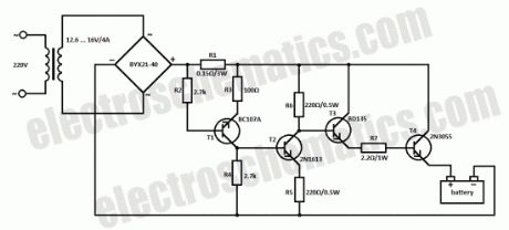
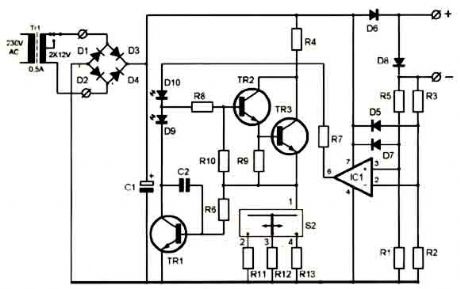
This car battery charger circuit can be used to charge 12V and 6V batteries. If it is used a transformer that can deliver 4A to 5A at a voltage between 12.6V and 16V then we can get rid of the switch for 6V or 12V batteries.
12V car battery charger circuit schematic
The car battery charging current is automatically limited to 4.2A. If there is a 600mV voltage on R1 (4A thru it), then the T1 transistor starts to conduct. Excessive charging current is avoided because the current value on T3′s base is limited. The difference between applied load current (at T4′s collector) and real voltage of the battery is balanced thru T4′s collector-emitter junction.
The power input of T4 (2N3055) is the product of load current and voltage difference already mentioned. When charging 6V car battery this power reaches a maximum of 40W. The rectifier diodes must be able to deliver 4A at 40V. T4 2N3055 must be mounted on a good heatsink in order to dissipate the heat.?
2 Responses to “Car Battery Charger with transistors”
Source: electroschematics.com
(View)
View full Circuit Diagram | Comments | Reading(3159)
Testatika Free energy
Published:2012/9/16 21:55:00 Author:Ecco | Keyword: Testatika, Free energy
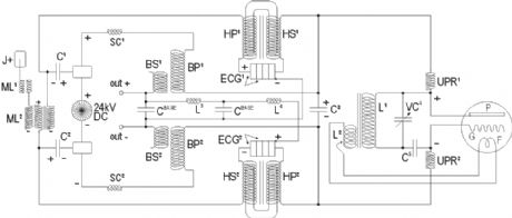
The Testatika design based on the Pidgeon/Wimshurst machine is of course only one type of electrostatic generator to build this system around. Since the early 1900s such power generators have come a long way in sophistication - and in power output - recently developed machines output 300,000 volts which can then be transformed and utilized. (View)
View full Circuit Diagram | Comments | Reading(4756)
Pulse-Charging Battery circuits
Published:2012/9/16 21:54:00 Author:Ecco | Keyword: Pulse-Charging Battery
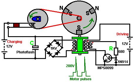
With this system, the rotor is started spinning by hand. As a magnet passes the triple-wound tri-filar coil, it induces a voltage in all three coil windings. The magnet on the rotor is effectively contributing energy to the circuit as it passes the coil. One winding feeds a current to the base of the transistor via the resistor R. This switches the transistor hard on, driving a strong current pulse from the battery through the second coil winding, creating a North pole at the top of the coil, boosting the rotor on its way. As only a changing magnetic field generate a voltage in a coil winding, the steady transistor current through coil two is unable to sustain the transistor base current through coil one and the transistor switches off again. (View)
View full Circuit Diagram | Comments | Reading(3434)
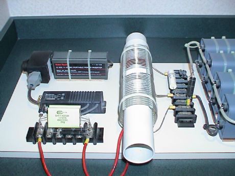
Kapanadze Free Energy Generator
Published:2012/9/16 21:52:00 Author:Ecco | Keyword: Kapanadze , Free Energy , Generator
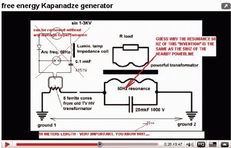
Georgia Republic inventor, Tariel Kapaladze, claims to have invented a 5 kilowatt free energy generator. In a demonstration video, the device appears to produce copious amounts of energy from no visible source. Though it appears to be extracting energy from the aether, some people think it could be a matter of getting energy from the electrical grid through inductive coupling. (View)
View full Circuit Diagram | Comments | Reading(6399)
Free Energy Circuit
Published:2012/9/16 21:50:00 Author:Ecco | Keyword: Free Energy
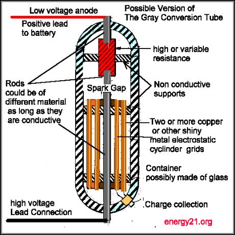
This type of design can produce a very high amperage current for a faction a second that can used to do some useful work if properly harnessed. A point to remember is that Paul Baumann built his first device in prison and as such did not have access to exotic materials as is often described in other theories of how the Testakica was said to have worked. One would conclude from this, that as such, that the home experimenter should also be able to build such a device from material from around the house. (View)
View full Circuit Diagram | Comments | Reading(1929)
Free energy Schematic II
Published:2012/9/16 21:49:00 Author:Ecco | Keyword: Free energy
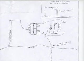
If you decide to use 2 circuits, i just connect their outputs together...neg output from first circuit to neg output of second circuit & pos output from first circuit to pos output of second circuit. And take readings from same place....from where you conected the 2 circuits together. (View)
View full Circuit Diagram | Comments | Reading(1498)
Motionless Pulsed Energy Generators
Published:2012/9/16 21:48:00 Author:Ecco | Keyword: Motionless Pulsed, Energy Generators
A solid-state electrical generator including at least one permanent magnet, magnetically coupled to a ferromagnetic core provided with at least one hole penetrating its volume; the hole(s) and magnet(s) being placed so that the hole(s) intercept flux from the permanent magnet(s) coupled into the ferromagnetic core. A first wire coil is wound around the ferromagnetic core for the purpose of moving the coupled permanent magnet flux within the ferromagnetic core. A second wire is routed through the hole(s) penetrating the volume of the ferromagnetic core, for the purpose of intercepting this moving magnetic flux, thereby inducing an output electromotive force. A changing voltage applied to the first wire coil causes coupled permanent magnet flux to move within the core relative to the hole(s) penetrating the core volume, thus inducing electromotive force along wire(s) passing through the hole(s) in the ferromagnetic core. (View)
View full Circuit Diagram | Comments | Reading(2197)
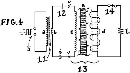
Free Energy device
Published:2012/9/16 21:48:00 Author:Ecco | Keyword: Free Energy
This is a simple straight forward machine that was basically designed in the 1890's by Nikola Tesla and modified for modular circuitry by Don Smith. There are so many ways to do this that it boggles the mind, but this circuit will power what you need. This setup with a 120v-30 amp isolation transformer is capable of 3600 watts continuous before overheating the transformer! It will handle much larger transformers and multiple transformers. (View)
View full Circuit Diagram | Comments | Reading(5477)
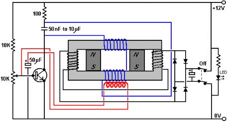
Free energy Battery Charger
Published:2012/9/16 21:46:00 Author:Ecco | Keyword: Free energy , Battery Charger

With this system, the rotor is started spinning by hand. As a magnet passes the triple-wound tri-filar coil, it induces a voltage in all three coil windings. The magnet on the rotor is effectively contributing energy to the circuit as it passes the coil. One winding feeds a current to the base of the transistor via the resistor R. This switches the transistor hard on, driving a strong current pulse from the battery through the second coil winding, creating a North pole at the top of the coil, boosting the rotor on its way. As only a changing magnetic field generate a voltage in a coil winding, the steady transistor current through coil two is unable to sustain the transistor base current through coil one and the transistor switches off again. (View)
View full Circuit Diagram | Comments | Reading(13240)
Simple self-powered circuit
Published:2012/9/16 21:46:00 Author:Ecco | Keyword: simple self-powered
This simple circuit is started running by connecting a twelve volt battery across the terminals, causing the large diameter Light-Emitting Diode to light up. When the battery is removed, the LED stays lit up because the circuit has become self-powering. While, at this scale, this is not a particularly useful project, it is an interesting one because conventional science says that it is quite impossible to do this. (View)
View full Circuit Diagram | Comments | Reading(2911)
12V Analogue Battery Volt Meter
Published:2012/9/16 20:50:00 Author:Ecco | Keyword: 12V , Analogue Battery , Volt Meter
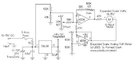
This circuit is used to measure the voltage on a 12V (nominal) lead acid rechargeable battery system. It was specifically designed for use in solar powered systems, but is general enough that it can be used for automotive or other 12V systems. Lead acid batteries normally spend their working lifetime in the voltage range of 11-15 Volts. This meter circuit was designed to show the voltage range of 10-15V on an analog meter movement, it can be used to show the battery charge state from empty to full. (View)
View full Circuit Diagram | Comments | Reading(1861)
0-30 Volts / 2,5A Variable Power Supply
Published:2012/9/13 20:37:00 Author:Ecco | Keyword: 0-30 Volts / 2,5A , Variable Power Supply
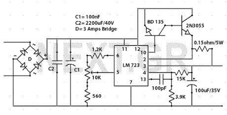
This is a high quality power supply with a continuously variable stabilized output adjustable between 0 and 30VDC. the LM 723 is the heart of the power supply which drives the BD137 and then the 2N3055. The circuit provides short circuit protection. And has great stability at voltage changes.
Source: NEXT.GR (View)
View full Circuit Diagram | Comments | Reading(2805)
High Voltage Power Supply 10kV
Published:2012/9/12 20:47:00 Author:Ecco | Keyword: High Voltage , Power Supply , 10kV
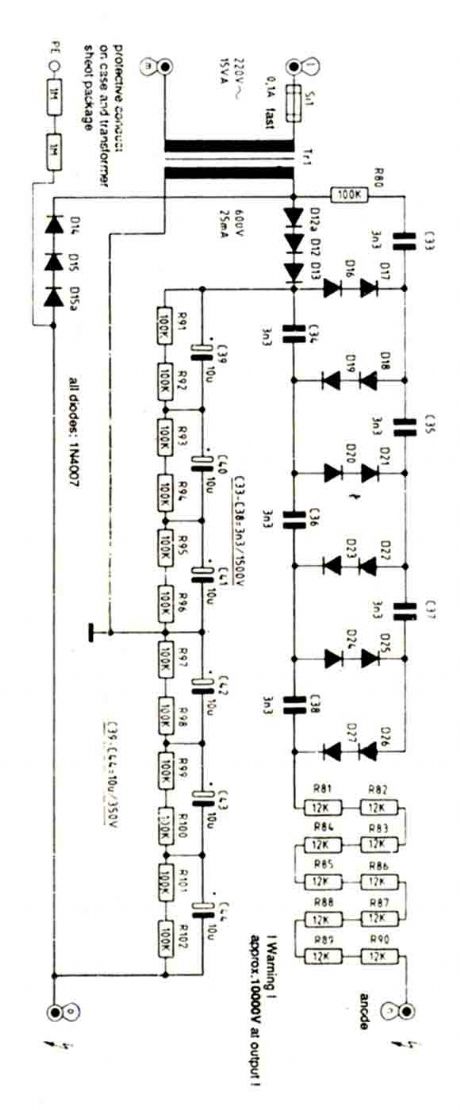
Be very carefull with this power supply because uses 220V mains and has 10KV at output. (View)
View full Circuit Diagram | Comments | Reading(1604)
Ni-Cd Baterry Charger 12-18V
Published:2012/9/12 20:44:00 Author:Ecco | Keyword: Ni-Cd , Baterry Charger, 12-18V
A clever charger circuit that safely can charge any Ni-Cd battery. Offers charge current sellection, polarization detection and protection and the ability to connect many batterys in siries. Ni-Cd bateries can be recharged more than 1000 times before become useless. the charging current shoud be the 1/10 of the (Ah) of the battery. The bateries need 14 hours to be fully charged. (View)
View full Circuit Diagram | Comments | Reading(3892)
5 VOLT MOMENTARY OPERATION TOUCH SWITCH
Published:2012/9/9 21:19:00 Author:Ecco | Keyword: 5 VOLT, MOMENTARY OPERATION , TOUCH SWITCH
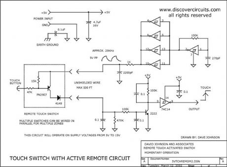
This simple circuit uses a single IC to form a nice touch switch circuit. A single transistor forms the remote active switch sensor. Multiple switches can be wired in parallel. The switch circuit can be located about 500 feet from the control circuit.
Source: discovercircuits (View)
View full Circuit Diagram | Comments | Reading(0)
Miniature 5v Line Powered Isolated Supply
Published:2012/9/9 21:05:00 Author:Ecco | Keyword: Miniature 5v , Line Powered, Isolated Supply

Often a circuit requires a 5v DC supply to power some logic circuits. The conventional method is to use an AC wall adapter. But, many systems, which bring AC power onto a circuit board, need a small AC to DC power supply right on the circuit board. The circuit below provides such a supply. It uses a classic series capacitor charge pump which acts as a current limiting device.
Source: discovercircuits (View)
View full Circuit Diagram | Comments | Reading(3451)
Wave Power Generator Demo System
Published:2012/9/6 20:49:00 Author:Ecco | Keyword: Wave Power Generator, Demo System
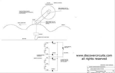
An inexpensive stepper motor is used as a voltage generator in this wave generator demo.
Source: discovercircuits (View)
View full Circuit Diagram | Comments | Reading(1907)
Battery Charge Current Indicator
Published:2012/9/6 20:01:00 Author:Ecco | Keyword: Battery Charge , Current Indicator
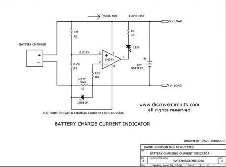
This circuit turns on a LED whenever it detects at least 25ma of battery charge current.
Source: discovercircuits (View)
View full Circuit Diagram | Comments | Reading(0)
CAPS PROVIDE VOLTAGE BOOST TO SERIES REGULATOR
Published:2012/9/5 21:05:00 Author:Ecco | Keyword: CAPS , VOLTAGE BOOST , SERIES REGULATOR

This circuit adds some capacitors and diodes to a traditional transformer type series regulator circuit to extend the normal operating range. It can insure regulation during low line voltage conditions or it can squeeze a few more watts out of a plug-in-the-wall power adapter power supply.
Source: discovercircuits (View)
View full Circuit Diagram | Comments | Reading(0)
18v AC to DC Power Supply
Published:2012/9/5 21:04:00 Author:Ecco | Keyword: 18v, AC to DC, Power Supply
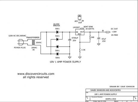
This is a classic linear power supply which produces a regulated 18v, rated at about 1 amp.
Source: discovercircuits (View)
View full Circuit Diagram | Comments | Reading(3047)
| Pages:46/291 At 204142434445464748495051525354555657585960Under 20 |
Circuit Categories
power supply circuit
Amplifier Circuit
Basic Circuit
LED and Light Circuit
Sensor Circuit
Signal Processing
Electrical Equipment Circuit
Control Circuit
Remote Control Circuit
A/D-D/A Converter Circuit
Audio Circuit
Measuring and Test Circuit
Communication Circuit
Computer-Related Circuit
555 Circuit
Automotive Circuit
Repairing Circuit