
power supply circuit
Index 40
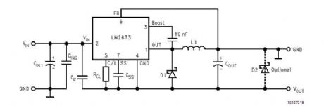
LM2673 Positive to Negative Converter
Published:2012/10/29 22:02:00 Author:muriel | Keyword: LM2673 , Positive to Negative Converter
View full Circuit Diagram | Comments | Reading(2269)
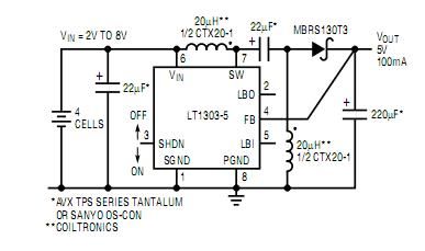
Micropower Buck/Boost Circuits, Part 2
Published:2012/10/29 22:00:00 Author:muriel | Keyword: Micropower Buck/Boost Circuits
View full Circuit Diagram | Comments | Reading(1048)
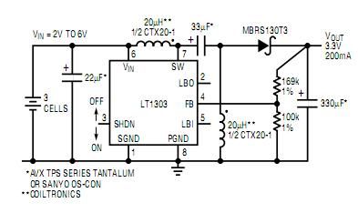
Micropower Buck/Boost Circuits
Published:2012/10/29 22:00:00 Author:muriel | Keyword: Micropower Buck/Boost Circuits
View full Circuit Diagram | Comments | Reading(1170)
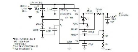
Single-Cell Li-Ion Battery to 2.5V Converter
Published:2012/10/29 21:59:00 Author:muriel | Keyword: Single-Cell, Li-Ion Battery , 2.5V Converter
View full Circuit Diagram | Comments | Reading(829)
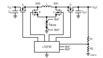
4-Switch Buck-Boost Converter
Published:2012/10/29 21:58:00 Author:muriel | Keyword: 4-Switch , Buck-Boost Converter
View full Circuit Diagram | Comments | Reading(2562)
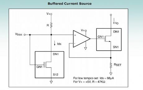
buffered current source
Published:2012/10/29 21:43:00 Author:muriel | Keyword: buffered current source
View full Circuit Diagram | Comments | Reading(896)
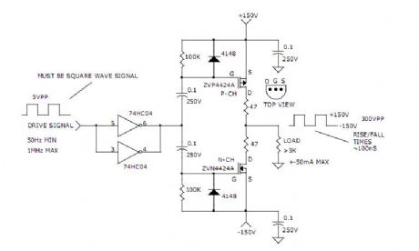
300V PEAK TO PEAK SIGNAL GENERATOR
Published:2012/10/29 21:39:00 Author:muriel | Keyword: 300V , PEAK TO PEAK , SIGNAL GENERATOR
View full Circuit Diagram | Comments | Reading(1150)
A simple step-up converter (6V to 12V)
Published:2012/10/29 1:43:00 Author:muriel | Keyword: A simple step-up converter, 6V to 12V
This step-up converter is intended for use in a '67 Citroen 2CV. This car, and I use the word loosely, has a 6V battery and won't support a modern radio that needs 12V. The circuit described here converts 6V to 12V at 1A sustained load current.
When the switch is closed an extra current flows through the inductance and stores energy there. The capacitor supplies the load with current during this time.
After the switch closes the capacitor is charged by the energy stored in the inductance and an extra current starts flowing through the load, causing the output voltage to rise (energy is supplied directly from the input source also as long as the diode is forward biased). During this time, the system behaves like a RLC-circuit, so, after a while, the current decreases. The switch is then closed again and the cycle repeats. One could say that charge is pumped from input to output, increasing the output voltage up to the point where there is an equilibrium between the discharging of the capacitor while the switch is closed and the charging by the inductor while the switch is open.
The output voltage equals (ton / toff + 1)ΧUin and is controlled by PWM of the switching action. (View)
View full Circuit Diagram | Comments | Reading(1887)
Two Transistor (Boy's Radio) Schematic and Theory of Operation
Published:2012/10/29 1:41:00 Author:muriel | Keyword: Two Transistor
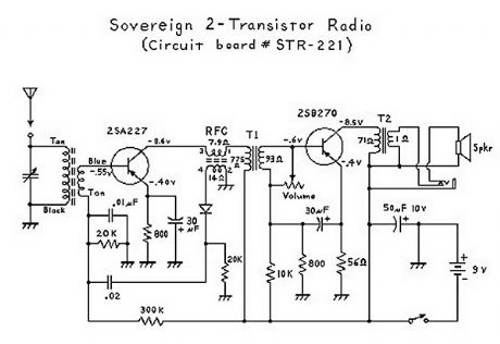
It has been interesting analyzing these radios. You have to give the Japanese credit for even making a radio that can drive a speaker with only 2 transistors! Basically, the first transistor (Q1) performs double-duty. It first acts as an RF amplifier, with some of the signal being fed back to the antenna coil to provide some regeneration for better selectivity and sensitivity. (This also results in a non-linear amplification of the signal which results in noticeable distortion.) The RF (radio frequency) signal is then rectified ( detected ) by the diode, and then the resultant audio signal is fed back to the base of the first transistor where it acts as the first AF (audio frequency) amplifier. (This is called a reflex circuit.) The audio signal is then fed through an interstage transformer to Q2 (the second transistor). The transformer provides impedance matching. The second transistor acts as a power amplifier, with the output signal going through an audio output transformer (to provide impedance matching again), and then finally to the speaker. Everything about this circuit is designed to provide maximimum gain; consequently there is no AGC (automatic gain control), and stronger stations come in a lot louder than weaker stations; unlike 6-transistor (or more) radio circuits which have an AGC circuit or function. (View)
View full Circuit Diagram | Comments | Reading(7628)
12V to 28V DC-DC Converter with LM2585
Published:2012/10/29 1:40:00 Author:muriel | Keyword: 12V to 28V, DC-DC Converter, LM2585
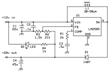
This boost regulator is for those times when you have a 28v relay, but want to use it with a 12v source. The circuit is built around the National Semiconductor LM2585, and uses the energy stored in an inductor to boost the 12v to 28. Output voltage can be varied by adjusting the ratio of resistor values on the feedback pin. (View)
View full Circuit Diagram | Comments | Reading(1592)
12v battery monitor
Published:2012/10/25 21:38:00 Author:muriel | Keyword: 12v battery monitor
View full Circuit Diagram | Comments | Reading(1844)
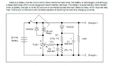
Battery Discharge Monitor
Published:2012/10/25 21:37:00 Author:muriel | Keyword: Battery Discharge Monitor
View full Circuit Diagram | Comments | Reading(1753)
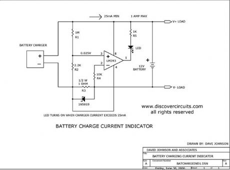
Battery Charge Current Indicator circuits
Published:2012/10/25 21:37:00 Author:muriel | Keyword: Battery Charge, Current Indicator circuits
View full Circuit Diagram | Comments | Reading(1975)
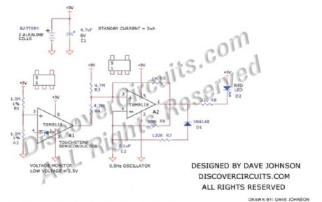
Alkaline Low Battery Voltage Indicator
Published:2012/10/25 21:36:00 Author:muriel | Keyword: Alkaline, Low Battery Voltage , Indicator
View full Circuit Diagram | Comments | Reading(1015)
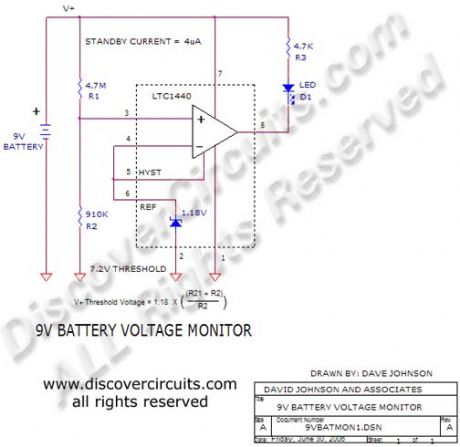
9v Battery Voltage Monitor
Published:2012/10/25 21:34:00 Author:muriel | Keyword: 9v , Battery Voltage Monitor
View full Circuit Diagram | Comments | Reading(994)
BattMan II: Build a Computer Controlled Battery Manager
Published:2012/10/25 21:32:00 Author:muriel | Keyword: BattMan II, Computer Controlled, Battery Manager
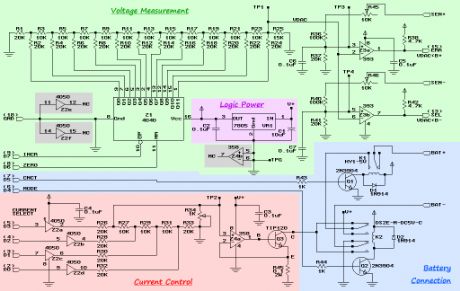
BattMan II consists of five subsystems: power supply, current control, battery connection, voltage measurement, and logic power.
The power supply I used is a commercial off-the-shelf model that can supply 18 Volts at 2.2 Amps. I purchased mine at a surplus store. Any similar power supply will do, so long as it produces 18 to 20 Volts, and enough current for the maximum charge rate you want to be able to use. Points labeled V+ in the schematic are connected to the positive terminal of the power supply.
CMOS buffers Z2a through Z2d together with resistors R26 through R34 form an R-2R ladder digital-to-analog converter. R34 is used to adjust the output voltage range so that it spans 0 to 0.2 Volts (which can be measured at test point TP2). The input to the converter is taken from the four low-order data bits (D0 to D3) of the parallel printer port that BattMan is connected to. (View)
View full Circuit Diagram | Comments | Reading(1530)
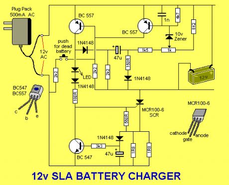
Battery Charger for 12V SLA
Published:2012/10/25 21:30:00 Author:muriel | Keyword: Battery Charger, 12V SLA
View full Circuit Diagram | Comments | Reading(2950)
AC power monitor circuit diagram
Published:2012/10/25 21:12:00 Author:Ecco | Keyword: AC power monitor
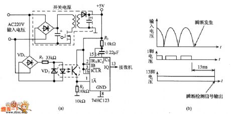
When AC power is suddenly turned off becauseof lightning strikes and other reasons, the important data stored in computer may disappear, so it needs to add short interruption power detection circuit to protect the memory data. AC220V voltage is rectified and regulated to get +5 V output voltage which is used as the working power of computer, but also working power of timer 74HC123. 74HC123's pin 13 is connected to the microcomputer. When AC power is normal, the 74HC123 timer resets, then output is in high level, computer works properly. When the AC power is anomaly, detection AC power occurs short interruptions with 15ms, then 74HC123's pin 13 output changes from the high to low level, then the computer will do data preservation work.
(View)
View full Circuit Diagram | Comments | Reading(3207)
Automatic Charger for Battery Operated Hi-Fi Preamps
Published:2012/10/25 21:28:00 Author:muriel | Keyword: Automatic Charger , Battery Operated Hi-Fi Preamps
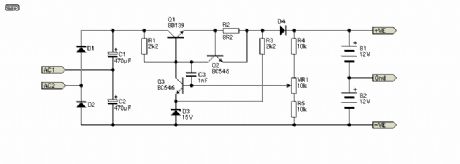
The charger is shown in Figure, and is a conventional (but very simple) regulator. A 3-terminal regulator is not suitable for this, as the voltage across it will be too high if the batteries are discharged. The charger uses a standard 15V transformer (which connects to the terminals marked ~In, Fig. 2), and uses a voltage doubler to provide a nominal 40V supply for the charger.
R1 provides current limiting so that heavily discharged batteries will not be damaged, nor damage the charger due to excessive current. Remember that Ni-Cd cells in particular should be charged at 0.1 x capacity - a 1AH (Ampere-Hour) cell should be charged at a maximum of 100mA (0.1 x 1).
As shown, the maximum current is limited to about 90mA - low enough for nearly all cells likely to be used for powering preamps and such. VR1 is used to set the float voltage, and this should be done as accurately as possible - a 10 turn pot is highly recommended to enable you to get an accurate setting. At 90mA, and with deeply discharged batteries, the dissipation in Q1 will be rather high - worst case is a little over 2 Watts, and a heatsink is essential. Should more current be needed, this is easily done by reducing the value of R2 - half the value will give double the current and vice versa. It is important that you ensure that the heatsink for Q1 is sufficient for the expected load current. C1 and C2 must be rated at a minimum of 50V - not because of the voltage, but to obtain a sufficiently high ripple current rating, especially when the charger is in current limit mode. (View)
View full Circuit Diagram | Comments | Reading(1344)
STMicroelectronics battery charger ICs
Published:2012/10/25 21:25:00 Author:muriel | Keyword: STMicroelectronics, battery charger ICs
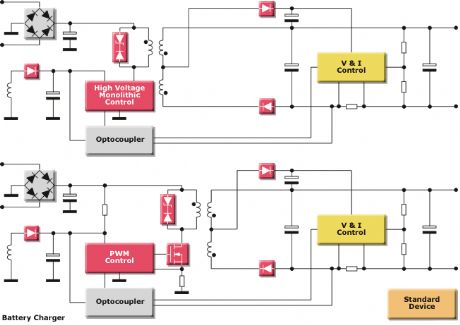
STMicroelectronics provides battery charger ICs and full solutions for cell phones, note books, digital cameras, hand tools and many other battery-powered applications. Several solutions are proposed to charge lithium-ion, nickel-metal hydride and nickel-cadmium batteries. Switched mode solutions are mainly used in portable or high power applications. The following block diagram shows a wide range of productsfor battery charger designs.
(View)
View full Circuit Diagram | Comments | Reading(1244)
| Pages:40/291 At 202122232425262728293031323334353637383940Under 20 |
Circuit Categories
power supply circuit
Amplifier Circuit
Basic Circuit
LED and Light Circuit
Sensor Circuit
Signal Processing
Electrical Equipment Circuit
Control Circuit
Remote Control Circuit
A/D-D/A Converter Circuit
Audio Circuit
Measuring and Test Circuit
Communication Circuit
Computer-Related Circuit
555 Circuit
Automotive Circuit
Repairing Circuit