
power supply circuit
Index 35
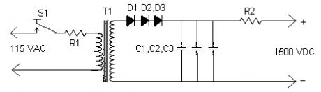
LASER Power Supply
Published:2012/12/11 0:40:00 Author:muriel | Keyword: LASER , Power Supply
View full Circuit Diagram | Comments | Reading(0)
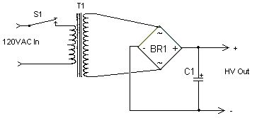
High Voltage High Current Power Supply
Published:2012/12/11 0:40:00 Author:muriel | Keyword: High Voltage , High Current, Power Supply
View full Circuit Diagram | Comments | Reading(757)
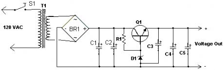
High Current Power Supply
Published:2012/12/11 0:39:00 Author:muriel | Keyword: High Current, Power Supply
View full Circuit Diagram | Comments | Reading(0)
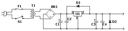
Fixed Voltage Power Supply
Published:2012/12/11 0:39:00 Author:muriel | Keyword: Fixed Voltage, Power Supply
View full Circuit Diagram | Comments | Reading(745)
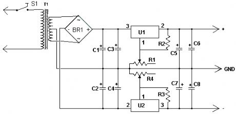
Dual Polarity Power Supply
Published:2012/12/11 0:39:00 Author:muriel | Keyword: Dual Polarity, Power Supply
View full Circuit Diagram | Comments | Reading(0)
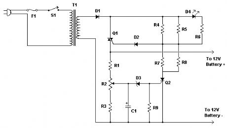
Car Battery Charger
Published:2012/12/11 0:38:00 Author:muriel | Keyword: Car , Battery Charger
View full Circuit Diagram | Comments | Reading(1105)
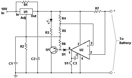
Automatic 12V Lead Acid Battery Charger
Published:2012/12/11 0:37:00 Author:muriel | Keyword: Automatic , 12V , Lead Acid Battery, Charger
View full Circuit Diagram | Comments | Reading(1015)
6V to 12V Converter
Published:2012/12/11 0:37:00 Author:muriel | Keyword: 6V to 12V, Converter

View full Circuit Diagram | Comments | Reading(1005)
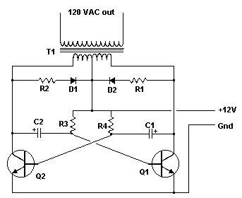
12V to 120V Inverter
Published:2012/12/11 0:36:00 Author:muriel | Keyword: 12V to 120V, Inverter
View full Circuit Diagram | Comments | Reading(894)
12V To 24V DC-DC Converter Circuit
Published:2012/12/11 0:35:00 Author:muriel | Keyword: 12V To 24V, DC-DC , Converter Circuit
View full Circuit Diagram | Comments | Reading(1689)
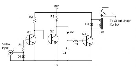
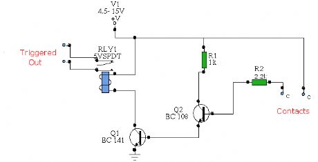
Video Activated Relay
Published:2012/12/11 0:32:00 Author:muriel | Keyword: Video Activated, Relay
View full Circuit Diagram | Comments | Reading(1012)
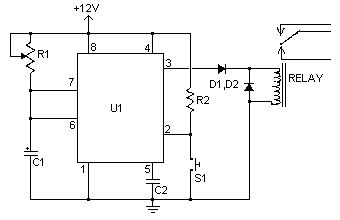
Time Delay Relay II
Published:2012/12/11 0:31:00 Author:muriel | Keyword: Time Delay , Relay
View full Circuit Diagram | Comments | Reading(940)
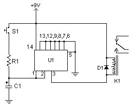
Time Delay Relay
Published:2012/12/11 0:30:00 Author:muriel | Keyword: Time Delay, Relay
View full Circuit Diagram | Comments | Reading(1017)
40W Fluorescent Lamp Inverter
Published:2012/12/10 0:50:00 Author:muriel | Keyword: 40W , Fluorescent Lamp, Inverter
View full Circuit Diagram | Comments | Reading(1174)
Two kinds of output switching power supply circuit diagram
Published:2012/12/7 1:24:00 Author:Ecco | Keyword: output , switching power supply
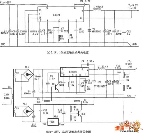
As shown in figure, it is a high-power switching power supply with L4970A. L4970A is a high-power single-chip switch integrated voltage regulator, the chip uses SIP-15 package, which is characterized by: ( 1 ) Input voltage must be > 11V, and the value is typically between 15 ~ 40V; ( 2 ) Output voltage: Fixed output is 5.1V, and it can also be set through an external circuit adjustable output with the range of 5.1 ~~ 40V; ( 3 ) the maximum output current is 10A; ( 4 ) operating frequency is 200kHz; ( 5 ) internal undervoltage detection, brownout reset power stage soft start circuit.
(View)
View full Circuit Diagram | Comments | Reading(1781)
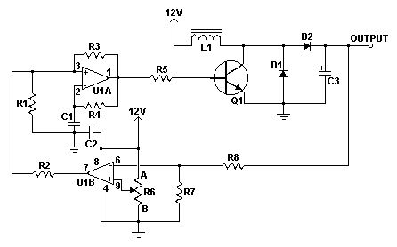
Step-up switching regulator power supply circuit
Published:2012/12/7 1:41:00 Author:Ecco | Keyword: Step-up , switching regulator , power supply
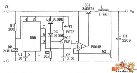
In the circuit, It uses transistor BG1 as a switching adjust tube; operational amplifier IC1 constitutes the compare amplifier; 555 time-base circuit is connected as astable multivibrator. Oscillator produces a sawtooth voltage on C1 (Vmin = 1/3Vz, Vmax = 2/3Vz, the frequency is determined by W1 and C1 ), then it is supplied to the noninverting input of the comparator IC1, sampling voltage is supplied to the inverting input terminal of comparator. The duty cycle of the rectangular waveform output by IC1 is decided by the sampling voltage, when the output voltage is a stable value, the sampled voltage is between 1/3Vz and 2/3Vz.
(View)
View full Circuit Diagram | Comments | Reading(3496)
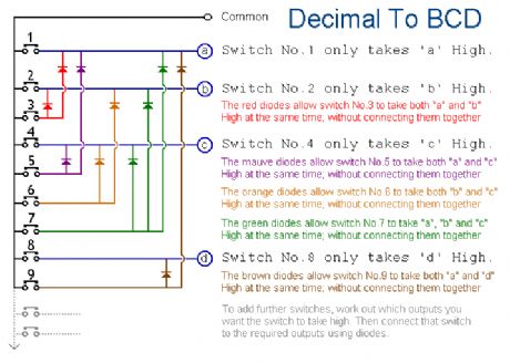
Decimal to BCD Convetor
Published:2012/12/3 20:20:00 Author:muriel | Keyword: Decimal to BCD Convetor

View full Circuit Diagram | Comments | Reading(878)
Temperature Controlled Relays
Published:2012/11/29 0:42:00 Author:muriel | Keyword: Temperature Controlled Relays
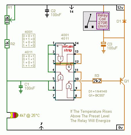
View full Circuit Diagram | Comments | Reading(925)
Light Controlled Relays
Published:2012/11/29 0:40:00 Author:muriel | Keyword: Light Controlled, Relays

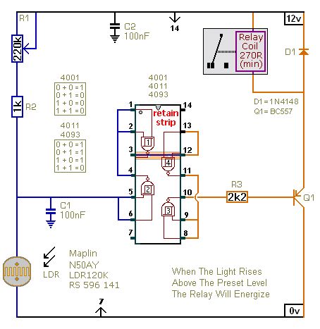

View full Circuit Diagram | Comments | Reading(829)
Water Activated Relay
Published:2012/11/29 0:33:00 Author:muriel | Keyword: Water Activated Relay
View full Circuit Diagram | Comments | Reading(942)
| Pages:35/291 At 202122232425262728293031323334353637383940Under 20 |
Circuit Categories
power supply circuit
Amplifier Circuit
Basic Circuit
LED and Light Circuit
Sensor Circuit
Signal Processing
Electrical Equipment Circuit
Control Circuit
Remote Control Circuit
A/D-D/A Converter Circuit
Audio Circuit
Measuring and Test Circuit
Communication Circuit
Computer-Related Circuit
555 Circuit
Automotive Circuit
Repairing Circuit