
Switching-Regulator Circuit
Index
LED lighting switch power drive circuit
Published:2013/12/17 2:19:00 Author: | Keyword: LED lighting switch power drive circuit,
Lighting of high power white LED is a new type of lighting energy saving as a major breakthrough for each, because the technology is not mature at present stage, its not ten points of energy saving effect is obvious. In this case, the LED drive circuit of the power conversion efficiency is a priority problem, for this choice as driving circuit switch power supply scheme.
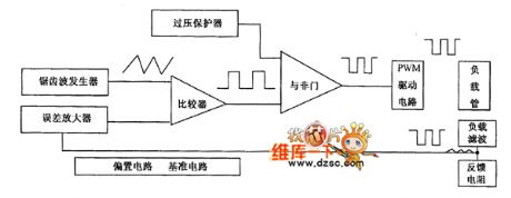
Practical people designed a dedicated to drive in high power LED switching power supply, its principle as shown. It chooses to switch tube in series with load and the perceptual component, with the capacitive element in parallel type Buck switching converter as the main circuit configuration, the current feedback at the same time, realize the decompression, filtering, steady flow.
The electricity output of the circuit flows through the feedback resistance detection, sampling, and form the feedback signal, feedback signal input to produce a reference voltage of the error amplifier, a reference voltage to cut fixed cycle amplitude of sawtooth wave modulation, formed by the comparator PWM (pulse width modulation) signal. PWM signal amplifying, drive pipe load switch, pulse drive current is produced. Because the output is dc, so add the appropriate external components for filter rectifier load. Load current changes, negative feedback effect of the circuit will change the size of the output duty cycle to achieve the pulse width modulation. Power supply voltage to prevent accidental, fire load tube, also designed the over-voltage protection circuit in the circuit, the circuit when abnormal tube shut off the output load.
Figure principle block diagramThis kind of high power white LED for driving integrated circuit, with a few simple external components that can form a complete pulse modulation type switching power supply, dc constant current output. Integrated circuit can realize frequency is 83 kHz, range of 110 ~ 2720 mA (adjustable) constant current output, voltage ripple and temperature change effect is good.
(View)
View full Circuit Diagram | Comments | Reading(1116)
5V / 10A regulator circuit
Published:2013/3/20 1:27:00 Author:Ecco | Keyword: 5V / 10A regulator
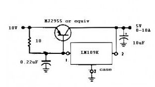
This power supply regulator circuit can provide current up to 10 amperes at a voltage 5 V.
The circuit is built from a complete 5V regulator IC LM 109 series from National Semiconductor. While for the current amplifier assisted by the PNP type transistor MJ 2955.
(View)
View full Circuit Diagram | Comments | Reading(1949)
5V / 3A Regulator
Published:2013/3/20 1:26:00 Author:Ecco | Keyword: 5V / 3A Regulator
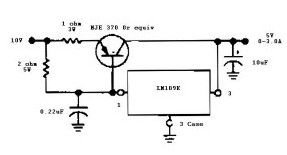
This regulator power supply schematic diagram is the same as the previous 5V 10A regulator circuit with a little modification and have the ability to supply less current up to 3 amperes at voltage of 5V.
The circuit is built from a complete 5V regulator IC LM 109 series from National Semiconductor. While for the current amplifier using a PNP type transistor MJE 370.
(View)
View full Circuit Diagram | Comments | Reading(1512)
5V / 4A Regulator Circuit
Published:2013/3/20 1:26:00 Author:Ecco | Keyword: 5V / 4A , Regulator
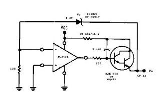
This is the other power supply regulator circuit, is different from the previous circuit, this using IC op amp quad type MC 3401 operational amplifier from Motorola. Here is also used NPN Epitaxial Silicon Darlington Transistor MJE 800.
(View)
View full Circuit Diagram | Comments | Reading(1489)
Non-isolated switching power supply circuit diagram
Published:2011/7/27 22:44:00 Author:Nicole | Keyword: switching power supply
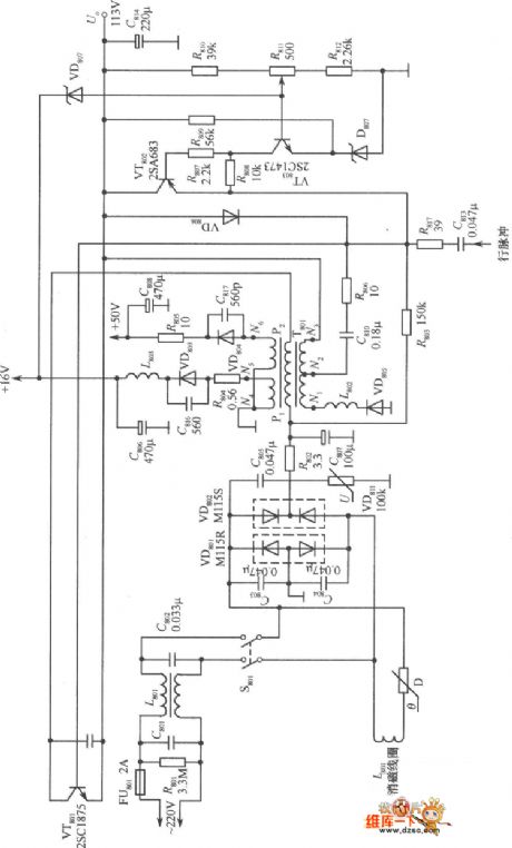
This is a useful non-isolated switching power supply circuit, it is used as the switching power supply of Peony TC - 483D color, including grid filter composed of C80l, C802, bridge rectifier circuit made of VD80l, VD802, a filter composed of R802, C807, peak voltage limiter composed of the varistor VD811; pulse oscillator consists of switch VT80l, pulse transformer T801; pulse width modulator made of VT802; error amplifier made of VT803.
It's not difficult to see from the figure, passing through the rectifier filter, 220V AC voltage is connected to output side directly by the primary winding of pulse transformer T801 and switch VT801, there is no isolation. The power supply has 16V, 50V and 113V three kinds of DC voltage output. When VT80l turns on, 113V DC output voltage will supply power to the load, while store electrical energy in C814 and magnetic energy in T801. When VT80l cut off, the N1 ~ N3 windings will produce the induced voltage with left negative and right, to make VD805 positive-skewed on, the energy stored in transformer will supply power to the load and charge to C814; C814 and L80l composition filter circuit, to make the 113V output voltage continuous and smooth.
(View)
View full Circuit Diagram | Comments | Reading(2362)
AC switch circuit diagram using optical controlling
Published:2011/10/18 3:31:00 Author:Rebekka | Keyword: optical control , AC switch
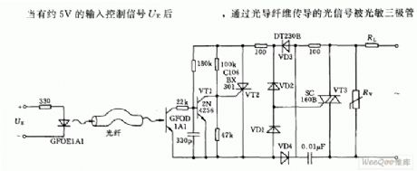
When it has 5V input control signal UE,optical signals pass optical fiber transmission. (View)
View full Circuit Diagram | Comments | Reading(1582)
Regulator DC-DC Circuit and Pin of Power Supply Monitor and its Main Features-MAX608
Published:2011/9/13 3:02:00 Author:Zoey | Keyword: Regulator, DC-DC Circuit, Power supply, High-efficiency Controller
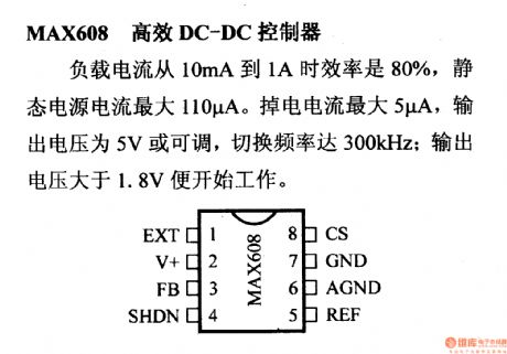
Ifload current of MAX608 high-efficiency DC-DC controller ranges from 10mA to 1A, its efficiency will be 80% and static current of power supply will be 110µA. For this controller, the maximum power-off current is 5µA, output voltage is 5V or adjustable, the switching frequency can reach 300kHz. This controller will begin towork as soon as voltage exceed 1.8V.
(View)
View full Circuit Diagram | Comments | Reading(855)
Regulator DC-DC Circuit and Pin of Power Supply Monitor and its Main Features-MAX603/MAX604
Published:2011/9/13 2:49:00 Author:Zoey | Keyword: Regulator, DC-DC Circuit, Pin of Power Supply Monitor, Linear Regulator
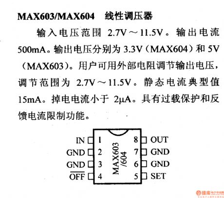
The input voltage range of MAX603/MAX604 linear regulator is 2.7V~11.5V. Its output current is 500mA, output voltage of MAX604 is 3.3V, MAX603 5V. External resistance regulator can be used to adjust output voltage, the adjusting range is 2.7V~11.5V. Typical value of static current is 15mA, power-off current is 2µA.This regulator has such functions as overload-proof and restrictions on feedback current. (View)
View full Circuit Diagram | Comments | Reading(1526)
Same Frequency Detection Circuit of Low Frequency and Small Drift Polarity Converting Type
Published:2011/8/25 22:48:00 Author:Michel | Keyword: Same Frequency, Detection Circuit
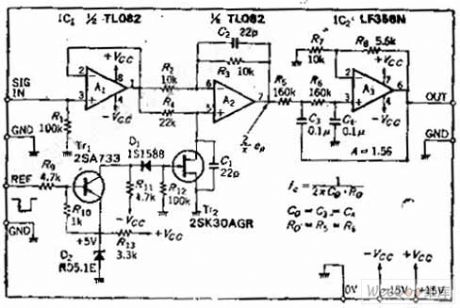

Circuit's Functions
The synchronous detection circuit with reverse phase or same phase whose work frquency is lower than dozens of HZand theycan be adpoted in the whole low frequency band.The circuit's analog switch uses the general N channel J-an FET. Smooth circuit adds12DB/OCT low-pass filter,which shortens the response time.It is easy to eliminate higher harmonic because the detection uses total wave rectifier system.This circuit is widely used in the lock-in amplifier detection circuit of measuring tiny voltage.
Circuit's Work Principle
OP amplifier A1 is impedance buffer ,A1 can be removed if the former stage's output impedance is as low as OP amplifier. (View)
View full Circuit Diagram | Comments | Reading(1132)
A Circuit Diagram of Discrete Elements of the Touch Switch
Published:2011/9/3 20:08:00 Author:Zoey | Keyword: Circuit Diagram, Discrete Elements, Touch Switch
The circuit of discrete elements of the touch switch has been shown in picture below. This circuit is composed of an induction magnifier, a memorizer and an AC driver. As soon as a finger touches the insulted plate, a small AC signal will be added to the gate of Tr1, the signal will produce square wave on R4 after being magnified, and then it will charge to C3 through Tr3, after that it will produce direct input voltage on R8, the voltage will be added to single crystal transistor Tr6. Finally, Tr6 will give rise to remittent oscillation and trigger the controllable silicon. The longer the switch is touched, the larger of voltage on R8 will be. As soon as the finger leaves the switch, load will be cut off. (View)
View full Circuit Diagram | Comments | Reading(1172)
Two On-off Circuits controlled by CMOS System Direct Motor
Published:2011/9/3 10:22:00 Author:Zoey | Keyword: On-off Circuits, CMOS System, Direct Current, Motor

Circuit (a) is controlled by 24-V and 18-A direct current motor CMOS. NPN reset tube 2N282 needs to get 20A current, and Q1 150mA. Circuit (b) is controlled by CMOS direct current motor that can input high level, the Darlington uses a PNP 2N6285,collector power of the incentive transistor Q1 is not connected to CMOS power, instead, it should be connected to the TV power. (View)
View full Circuit Diagram | Comments | Reading(1320)
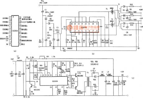
Application of PWM-based Switching-Regulator Power Controller SG3524
Published:2011/9/8 6:20:00 Author:Felicity | Keyword: PWM, Switching-Regulator, Power Controller
View full Circuit Diagram | Comments | Reading(8722)
Boosting Switching-Regulator Power Circuit Composed of 555
Published:2011/9/8 6:14:00 Author:Felicity | Keyword: Boosting, Switching-Regulator Power Circuit
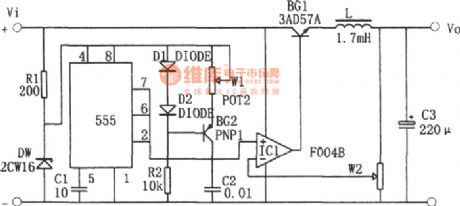
In the circuit, BG1 is the switch-adjusting transistor; operational amplifier IC1 composes the comparison amplifier; 555 time-base circuit is connected as astable multivibrator. The saw-wave voltage produced by the oscillator on C1 (Vmin=1/3Vz, Vmax=2/3Vz, the frequency determined by W1 and C1) is put onto the noninverting-terminal of the comparison amplifier IC1 and the sampling voltage is put onto the inverting-terminal of the comparison amplifier. (View)
View full Circuit Diagram | Comments | Reading(3314)
Power Conversion Circuit Of Switching Regulator Power
Published:2011/8/23 23:40:00 Author:Robert | Keyword: Power, Conversion, Switching, Regulator
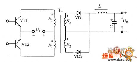
The power conversion circuit of switching regulator power has many types such as push-pull, full-bridge, half-bridge and single-ended flyback and single-ended forward and other types. The picture shows the push-pull type power conversion circuit. The control circuit would control the base electrode of the transistors VT1 and VT2. The VT1 and VT2 would be alternately connected and disconnected with PWM excitation method. Then they would convert the input DC voltage to the high-frequency square-wave AC voltage. When the VT1 is conducted, the input power voltage Ui would be through VT1 and then it is added the high-frequency transformer T1's primary winding N1. Because T1 has two main windings N1 with equal number of turns, so when the VT1 is conducted, it adds twice power voltage 2UI onto the transistor VT2 which is in disconnected mode. (View)
View full Circuit Diagram | Comments | Reading(1006)
Regulator Power Circuit Using Luoya Improving Method
Published:2011/8/14 3:43:00 Author:Robert | Keyword: Regulator Power, Luoya, Improving, Method
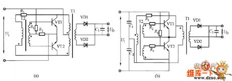
The picture shows the luoya improving method circuit. The picture (a) is suitable for the 220V input, while the picture (b) is suitable for the 380V input. For example in the circuit of picture (a), if firstly make the VT1 conducted by starting the resistor R1, the transformer T1 would have excitation and add the voltage on the transformer T2 through the current-limiting resistor R3. So the VT1 would be conducted rapidly. Then is the T1 is saturated, the VT1 would disconnected and at the same time the T2 would generate the opposing electromotive force and VT2 is conducted. So the VT1 and VT2 would make the oscillation by their alternate connected and disconnected work.
(a)Suitable for 220V input. (b)Suitable for 380V input.
The picture shows the luoya improving method circuit. (View)
View full Circuit Diagram | Comments | Reading(903)
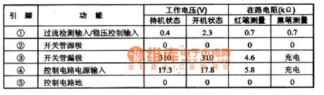
STR-F6454R Switching power supply thick film integrated circuit diagram
Published:2011/8/8 0:23:00 Author:Sophia | Keyword: Switching power supply, thick film integrated circuit
(View)
View full Circuit Diagram | Comments | Reading(1494)
±15V_SYMMETRICAL_AT_1A
Published:2009/7/19 23:06:00 Author:Jessie
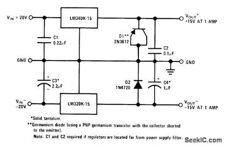
Connectionshown gives same lineand load regulation characteristics as for individual regulators. D1 ensures start-up of LM340K.15 under worst-case conditions of common load and 1.A load current over full temperature range.- Linear Applications, Vol. 2, National Semiconductor, Santa Clara, CA, 1976, AN-103, p 8. (View)
View full Circuit Diagram | Comments | Reading(1072)
The morning and night light-operated switch circuit diagram with 10-10LX light intensity
Published:2011/8/3 2:42:00 Author:Rebekka | Keyword: morning and night , light-operated switch , 10-10LX light intensity
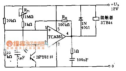
The power of 8.5KW load off can be controlled by using the input phototransistor BPY62 and power operational amplifier.The voltage divider composed of two 10KΩ resistors connects to the inverting input terminal of the voltage divider, so that the turnover voltage of the amplifiers is 1/2 US. Switch sensitivity can be adjusted in the range of 10 - 10 quadruplicate lx by using potentiometer. The output of the circuit is controlled by contactor coil. (View)
View full Circuit Diagram | Comments | Reading(1629)
A Circuit of Crystal Switched Transistor Bridge Direct Current and Servo Electronic Machines
Published:2011/8/1 2:15:00 Author:Zoey | Keyword: Switched, Crystal, Transistor Bridge, Direct Current , Servo Electronic Machines
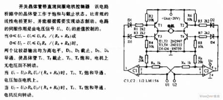
Transistors of this bridge circuit only works in saturated and ceased state. It has a better regular linearity bridge than usual ones, and it can achieve dynamic brakeif needs to. Servoeffect ofthis circuit is controlled by thevoltage signal margin ofU1 andU2.
when 0≤U1-U2≤U1RA/(RA+RB) or0≤U2-U1≤U2RA/(RA+RB),
both comparator will input highlevel, D1and D2 will cease to work, D3 and D4 will conduct, making T1 and T2 cease to work,T3 and T4 be saturated, the motor will not be able torotate without voltage.
When U1-U2>RAU1/(RA+RB),T3 and T2 will turn to be saturated and will conduct, the voltage will be added on the motor.
When U2-U1>RAU2/(RA+RB),T1 and T4 will turn to be saturated and will conduct, the motor will rotate reversely. (View)
View full Circuit Diagram | Comments | Reading(1254)
Half-bridge switching regulated power supply circuit composed of CW1524
Published:2011/5/10 1:44:00 Author:Rebekka | Keyword: Half-bridge switching regulated power supply
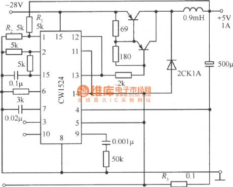
Half-bridge switching regulated power supply circuit composed of CW1524 is shown as above. (View)
View full Circuit Diagram | Comments | Reading(1248)
| Pages:1/8 12345678 |
Circuit Categories
power supply circuit
Amplifier Circuit
Basic Circuit
LED and Light Circuit
Sensor Circuit
Signal Processing
Electrical Equipment Circuit
Control Circuit
Remote Control Circuit
A/D-D/A Converter Circuit
Audio Circuit
Measuring and Test Circuit
Communication Circuit
Computer-Related Circuit
555 Circuit
Automotive Circuit
Repairing Circuit