
Sensor Circuit
Index 22
Thyristor driving circuit
Published:2011/6/8 20:33:00 Author:Christina | Keyword: Thyristor, driving
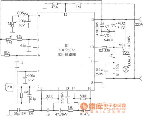
This circuit is composed of the novel pyroelectric infrared sensing specific device TDH98072. This control circuit has the advantages of simple circuit, easy to adjust and high reliability. And this device can be used to assemble other control circuits such as the anti-theft alarm, the automatic control lights and the automatic water valve.etc. The photoconductive resistance CdS uses the light resistance which is lower than l00kΩ or the dark resistance which is higher than 3.3MΩ. The pyroelectric infrared sensor PIR can use any kinds of small pyroelectric probe such as the ANM1 type. (View)
View full Circuit Diagram | Comments | Reading(1113)
All-round tracking solar electronics circuit
Published:2011/6/8 21:01:00 Author:Christina | Keyword: All-round, tracking, solar, electronics
Working principle: the solar device which uses the photovoltaic cells needs to have the sun tracking function, or the efficiency will be greatly reduced. Here we introduce the device, you can track the horizontal and vertical direction of the sun by using it, at night it will automaticly reset. If you want to track the sun, you need the sun light probe. As the figure shows, the sun light probe of this device is composed of a convex lens, five photoconductive resistances, a control circuit board and a cylinder.
(View)
View full Circuit Diagram | Comments | Reading(890)
Camera internal flash circuit
Published:2011/6/8 21:16:00 Author:Christina | Keyword: Camera, internal, flash circuit
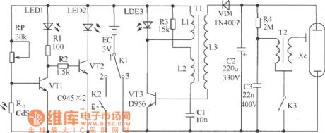
This circuit is composed of the light measurement circuit and the flash circuit, as the figure shows. It can be used in the POPTICS (one kind of popular integration camera), the Franka X-500 and the WIZEN-860S cameras. It is composed of the following circuits:
(1)the light measurement circuit is composed of the VT1, VT2 and the light metering component RG (use the cadmium sulphide CdS photoconductive resistance).
(2)the electrical inductance three-point oscillator circuit is composed of the VT3, C1, T1, this circuit completes the transformation of DC low voltage→AC high voltage→DC high voltage to supply power for the flash light.
Components selection: the VT1 and VT2 use the C945 type transistor; the VT3 uses the D965 type transistor. The LEDl uses the Φ55mm red LED, the LED2 uses the Φ55mm green LED and the LED3 uses the Φ55mm yellow LED. The RG uses the CdS photoconductive resistance. The other components are as shown in the figure. (View)
View full Circuit Diagram | Comments | Reading(3360)
optical coupling V/F converter circuit
Published:2011/5/29 7:37:00 Author:chopper | Keyword: optical coupling, V/F converter
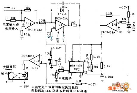
This circuit can convert 0~10V input voltage into corresponding frequency from the output end of optoisolator.When Convertor RM4151 and quad operational amplifier use together, they will has a high linearity.Quad operational amplifier,integraph,voltage regulator and LED driver.
(View)
View full Circuit Diagram | Comments | Reading(1873)
light control switch circuit with photosensitive resistor (LDR)
Published:2011/5/24 0:28:00 Author:John | Keyword: light control switch, photosensitive resistor
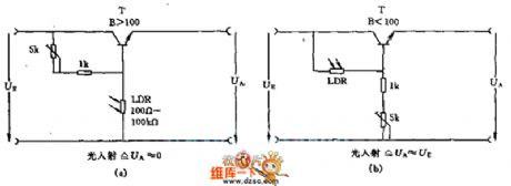
Where there is light, the transistor with photoresistor LDR in the circuit is connected in high power level or in zero level. The amplification factor of transistor β is sufficient if it is >100. And the resistance of photosensitive resistor would be between the 100Ω ~ 100KΩ. Such is arranged to be respectively corresponding to light irradiation situations and dark conditions. If it is expected to control a higher power load, it should use Darlington transistors.
(View)
View full Circuit Diagram | Comments | Reading(1937)
The luminous flux adjustment equipment circuit of light dependent resistors (LDR)
Published:2011/5/23 3:55:00 Author:Borg | Keyword: luminous flux, adjustment equipment circuit, light dependent resistors
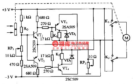
This is a luminous flux adjustment equipment circuit of light dependent resistors (LDR). This circuit is used to measure the luminous flux on the LDR, and adjusts it. If the luminous flux is growing, then the resistance of RG is decreasing, and the base LEV of VT1 and VT2 is rising, finally, VT1 is conducting and VT2 is blocked. At the moment, as VT1 and VT2 are Schmidt circuits, therefore, VT3 becomes conducting. Then the relay of KI takes action and its terminal of KI-I links with the power supply, and the motor runs, the silt is adjusted to make the luminous diminish. When the luminous flux reaches the regulated value, VTI is blocked and the motor stops running.
(View)
View full Circuit Diagram | Comments | Reading(1381)
TSV Type Temperature Sennor Typical Application Circuit
Published:2011/5/22 4:04:00 Author:Robert | Keyword: TSV Type, Temperature Sennor, Application
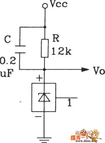
This circuit's output voltage Vo's temeratrue sensitivity is 10mV/°C. The resistance R is current-limit resistance. The capacitor C is used to improve the stability of the circuit. When the test position and the result-reading position have a far distance, the wire resistance's voltage drop would cause some extent measuring errors.
(View)
View full Circuit Diagram | Comments | Reading(812)
The luminous flux test circuit with optical resistors
Published:2011/5/20 0:55:00 Author:Borg | Keyword: luminous flux, test circuit, optical resistors
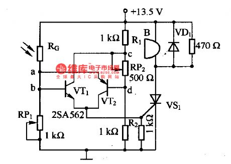
This is a luminous flux test circuit with optical resistors. In the circuit, the optical resistor RG forms a bridge with RP1,RP2,R1 and R2; RP1 is used to adjust the balance of the bridge; RP2 is used to adjust the sensitivity of the circuit. If we adjust RP1 to make the voltages on a and c are equal, then VTl and VT2 stop, and the thyristor of VSI is off. In the meantime, if the resistance of RG changes, the bridge will be unbalanced, and a voltage will be generated among a-c, then VTI and VT2 are on, the thyristor of VSI is also on, the buzzer B will buzz to inform the luminous flux of the test.
(View)
View full Circuit Diagram | Comments | Reading(1724)
The closing door reminder circuit (1)
Published:2011/5/23 4:43:00 Author:Borg | Keyword: reminder circuit
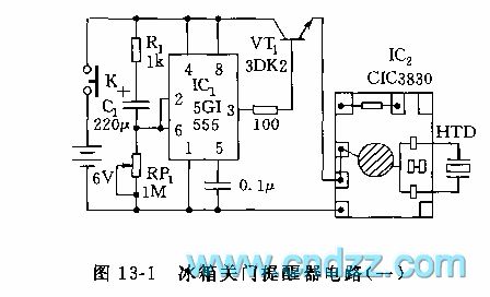
See as in Figure 13-1, the circuit consists of a trigger relay circuit and an integrated music circuit. When the fridge door is open, the touch switch (K) is linked to the power supply, as the voltage on the terminal of C1 can not be changed suddenly, on the trigger terminal 2-pin of 555, there is a positive peak voltage(>2/3VDD) trigger which can reset the circuit, and the 3-pin is in low LEV, so VT1 is blocked. The capacitor of C1 charges with R1 and RP1, when the voltage on the 6-pin is 1/3 VDD lower than trigger voltage, 555 will be posited and the 3-lead is in high LEV, then VT1 is conducting and IC2 gets power and make sounds to remind the master of opening the door.
Figure 13-1 The closing door reminder circuit (1) (View)
View full Circuit Diagram | Comments | Reading(1366)
photosensitive circuit of automatic batch scale ZD—30C and ZD-30D
Published:2011/5/16 3:35:00 Author:chopper | Keyword: automatic batch scale, photosensitive
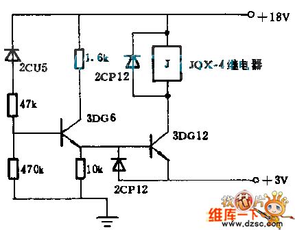
When light is dark,the dark-current is tiny,and 3DG6 as well as 3DG12 stops.The relay is of attonity.When the light is available,3DG6 as well as 3DG1 is conductive and relay actuates.Blanking door is controlled by the relay to realize the purpose that controlling baiting as the desired value.2CP12 is used to prevent the back-emf made by the release of relay.This automatic batch scale can fix value by scale mark of 0.5kg between 0 and30kg.The precision can reach one in a thousand.
(View)
View full Circuit Diagram | Comments | Reading(1019)
Celsius Thermometer Circuit Composed Of LM35DZ Celsius Temperature Sensor
Published:2011/5/17 9:06:00 Author:Robert | Keyword: Celsius, Thermometer, Temperature Sensor
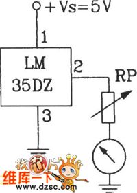
The Celsius Thermometer Circuit Composed Of LM35DZ Celsius Temperature Sensor is shown below.
(View)
View full Circuit Diagram | Comments | Reading(1472)
Precision Celsius Thermometer Circuit Composed Of SL134 Integrated Temperature Sensor
Published:2011/5/17 8:44:00 Author:Robert | Keyword: Precision, Celsius Thermometer, Integrated, Temperature Sensor
The Precision Celsius Thermometer Circuit Composed Of SL134 Integrated Temperature Sensor is shown below.
(View)
View full Circuit Diagram | Comments | Reading(1224)
Cooling liquid level sensor circuit diagram
Published:2011/5/16 20:30:00 Author:Nicole | Keyword: cooling liquid level, sensor
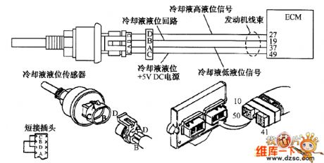
The cooling liquid level sensor circuit is shown in the figure.
In 49 terminal of motor wiring harness's 5V power line, the voltage is detected too high or too low, EOM is considered failure, these failures are recorded in the form of fault code 515 or 516, the yellow alarm indicator light is turned on. Whether the power voltage is too high or too low, it will lead to the motor loss the protection function of cooling liquid level.
(1)The motor wiring harness and cooling liquid level sensor connector terminal are checked, if it is damaged, it should be repaired.
(View)
View full Circuit Diagram | Comments | Reading(1539)
Wireless detector part circuit
Published:2011/5/17 1:34:00 Author:Christina | Keyword: Wireless, detector part
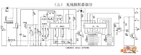
Wireless detector part circuit (View)
View full Circuit Diagram | Comments | Reading(992)
PH Meter Sensing And Measuring Circuit
Published:2011/5/16 20:04:00 Author:Robert | Keyword: PH Meter, Sensing, Measuring
View full Circuit Diagram | Comments | Reading(2880)
New TDH98072 dedicated pyroelectric infrared sensor circuit diagram
Published:2011/5/16 3:13:00 Author:Ecco | Keyword: New , dedicated , pyroelectric , infrared , sensor
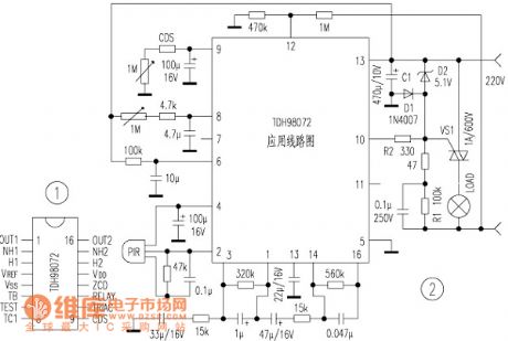
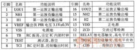
TDH98072 is a new pyroelectric infrared sensor specific devices. The output current of the circuit is high with PIR sensor input, and it can drive SCR, relay. In addition, the circuit uses CMOS process, the quiescent current is less than 1mA when it works. The control circuit composed of the circuit (such as burglar alarm, automatic lights, automatic valve) has the features of simple structure, easy adjustment, high reliability. 1. The shape and pin arrangement of TDH98072 are shown in Figure 1.
Photoresistor should select bright resistor(bright environment in the resistance) being less than 100kΩ, the dark resistance is greater than 3.3MΩ,pyroelectric infrared probe PIR can choose any small pyroelectric probes (must bring lens, such as ANM1 type), the other component parameters are shown in the figure.
(View)
View full Circuit Diagram | Comments | Reading(1600)
Electronic thermometer(2)
Published:2011/5/10 21:53:00 Author:Nicole | Keyword: electronic thermometer
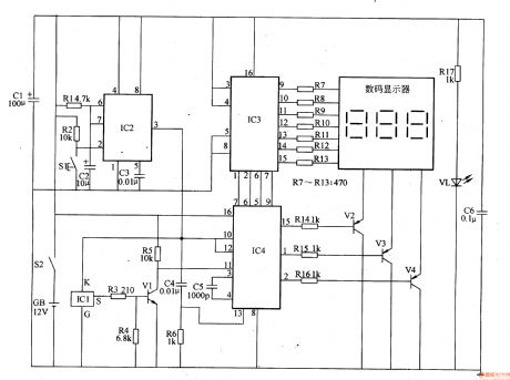
The temperature measuring range of this electronic thermometer is 0-50℃, the precision is 0.1℃, the measurement results are intuitively displayed by digital display.
The working principle of this circuit
This electronic thermometer circuit is composed of temperature detection circuit, monostable circuit, digital display drive circuit and power supply circuit, it is shown in the figure 9-133.
The temperature detection circuit is made of temperature sensor integrated circuit IC1, resistors R3-R5 and transistor V1.
The monostable circuit is composed of resistors R1, R2, capacitors C2, C3 and time base integrated circuit IC2.
The digital display drive circuit consists of digital display, counter integrated circuit IC3, decoding drive integrated circuit IC4, resistors R7-R16 and transistors V2-V4.
The power supply circut is composed of power supply switch S2, battery GB, filter capacitors C1, C6, current limiting resistor R17 and power supply indicator LED VL.
When the power supply switch S2 is turned on, one way of GB's 12V DC voltage is fed to IC2-IC4 by Cl、C6 filter, the other way is current limited and reduced voltage by R17 then to light up VL.
(View)
View full Circuit Diagram | Comments | Reading(6906)
Electronic thermometer(1)
Published:2011/5/10 21:31:00 Author:Nicole | Keyword: electronic thermometer
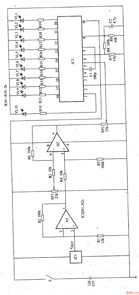
This electronic thermometer adopts temperature sensor to detect temperature, the measured temperature is displayed by LED. The temperature measuring range is 35-40T, the temperature resolution is 0.5℃(it can display 10 temperature values such as 35.5℃、36℃、36.5C…39℃、39.5℃、40℃).
The working principle of this circuit
This electronic thermometer circuit is composed of temperature measurement amplifier circuit, comparison amplifier circuit and temperature indication circuit, it is shown in the figure 9-132.
The temperature measurement amplifier circuit is made of temperature sensor IC1, operational amplifier IC2(Nl、N2) internal N1 and resistors R1, R2.
The comparison amplifier circuit is composed of resistors R3-R6, potentiometers RPl、RP2 and IC2 internal operational amplifier N2.
The temperature indication circuit consists of LED display drive IC3, resistors R7-R19, LED VLl-VLlO and capacitors C1, C2.
If the measured people's temperature is 36℃, VLl and VL2 turn on, and VL3-VLlO off; if the temperature is 37℃, then VLl-VL4 turn on, VL5-VLlO off; if the temperature is 38℃, then VLl-VL6 turn on, VL7-VLlO off, and so on.
(View)
View full Circuit Diagram | Comments | Reading(1331)
Electronic temperature sensor circuit with the 4-bit horizontal-vertical converter
Published:2011/5/12 20:47:00 Author:TaoXi | Keyword: Electronic temperature sensor, 4-bit, horizontal-vertical converter
Electronic temperature sensor circuit with the 4-bit horizontal-vertical converter (View)
View full Circuit Diagram | Comments | Reading(751)
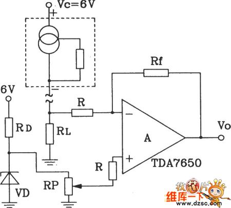
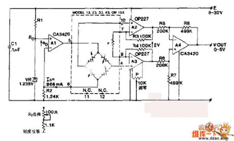
Digital telemetering thermometers FDD5 and JDD5
Published:2011/5/11 19:30:00 Author:TaoXi | Keyword: Digital telemetering thermometer
Transmitter circuit:
The temperature detecting circuit is composed of the temperature integrated sensor AD590, this circuit changes the temperature variation into the output current variation. AD590's output current is proportional to the measurement temperature, as the temperature increases, the output current increases with the 1μA/K constant ratio. When the output current gets through RP2, at the top of RP2 forms the voltage, and this voltage is amplified by the voltage amplifier and is used as the voltage-frequency changer's control voltage.
Receiving circuit: (View)
View full Circuit Diagram | Comments | Reading(682)
| Pages:22/27 At 2021222324252627 |
Circuit Categories
power supply circuit
Amplifier Circuit
Basic Circuit
LED and Light Circuit
Sensor Circuit
Signal Processing
Electrical Equipment Circuit
Control Circuit
Remote Control Circuit
A/D-D/A Converter Circuit
Audio Circuit
Measuring and Test Circuit
Communication Circuit
Computer-Related Circuit
555 Circuit
Automotive Circuit
Repairing Circuit