
Sensor Circuit
Index 25
MN12C25D Memory Integrated Circuit
Published:2011/5/8 22:38:00 Author:Sharon | Keyword: Memory, Integrated
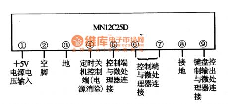
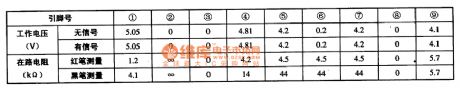
MN12C25D is memory integrated circuit produced by Matsushita, widely used in electronic products of Panasonic series, such as Panasonic color TV, air conditioning, DVD players and so on. 1. Features MN12C25D IC 's internal is mainly composed of the memory matrix, data and clock interface circuit, memory control circuit and other ancillary circuit. 2. Functions and data MN12C2SD IC is in 2.5 foot 9-pin single row of plastic package with its function as shown in the figure, and its operating parameters listed in Table.
(View)
View full Circuit Diagram | Comments | Reading(1939)
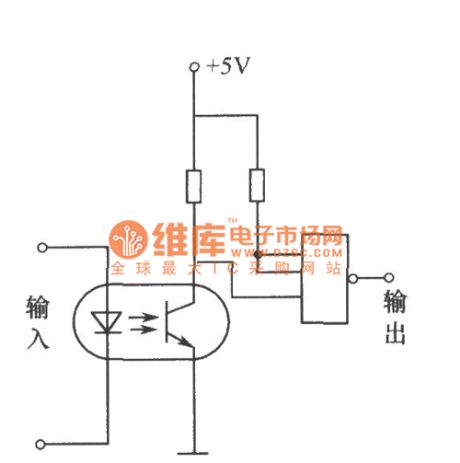
Schmidt Circuit of Photo-coupler
Published:2011/5/8 5:14:00 Author:chopper | Keyword: Photo-coupler , Schmidt Circuit
View full Circuit Diagram | Comments | Reading(941)
Homemade photo-couplers Circuit
Published:2011/5/5 2:06:00 Author:chopper | Keyword: photo-couplers
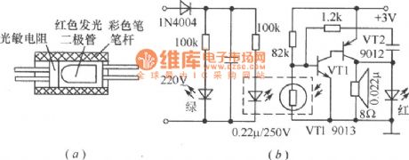
Combine the Φ55mm, red LED with photoresistance by transparent tape and put them in a pigmented penholder(black for good),and then seal both end,which has made a photo-coupler.Photo-coupler can applies to low frequency switch circuits ,just as shown in picture a.And picture b shows an outage alarm circuit adopting photo-couplers that can make an alarm if the electricity is not available.As usual,the red LED is ashine and the photo-coupler reduce the resistance of photoresistance through coupling.So,VT1 stops working,and the oscillator comprised by VT1、VT2 stops as well.When meet a commercial power cut, the resistance increases and makes VT1 connected,so that the oscillator starts to run,giving out a warning signal. (View)
View full Circuit Diagram | Comments | Reading(1120)
Piezoresistive integrated pressure sensor circuit
Published:2011/5/5 22:53:00 Author:Sharon | Keyword: Piezoresistive, integrated, pressure sensor
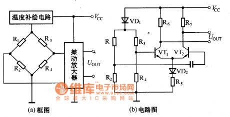
To deal with temperature drift of sensor's sensitivity, the general method of compensation is to change the supply voltage. With the development of semiconductor technology, there has emerged integrated piezoresistive pressure sensor, which is monolithic integrated pressure sensor composed of electric bridge formed by four sense resistors, the voltage amplifier, and the temperature compensation circuitry. The Graph is its circuit diagram and scheme. Owning to the temperature compensation circuit and differential amplifier that integrated pressure sensor applied, its sensitivity temperature coefficient is almost amount to zero. (View)
View full Circuit Diagram | Comments | Reading(1797)
Temperature Drift Compensation Circuit
Published:2011/5/6 1:33:00 Author:Sharon | Keyword: Temperature drift, Compensation
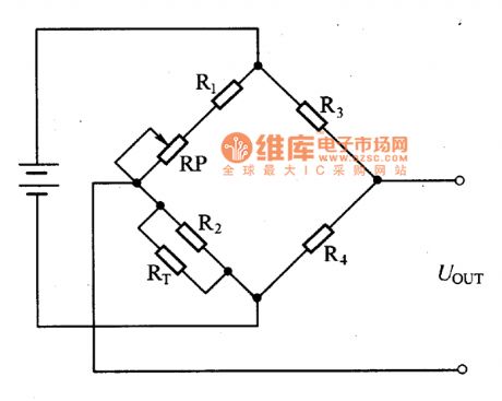
In order to solve the problem of temperature drift, for power supply on the electric bridge, it usually applies constant current source power supply.However, due to the production process and other reasons, the resistance of the bridge are not equal, and there is zero-bit output.So, even the constant current source power supply is applied, there still will be a certain temperature error.
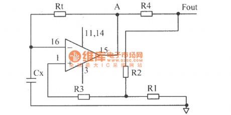
Piezoresistive pressure sensor not only has the phenomenon of zero-bit temperature drift, but also its sensitivity changes with temperature.Piezoresistive pressure sensor's zero drift can be solved by series and parallel of the thermistor in bridge circuit, as shown in the picture.RT is thermistor which is mainly used to compensate for zero drift; RP is used to adjust the zero output. (View)
View full Circuit Diagram | Comments | Reading(1418)
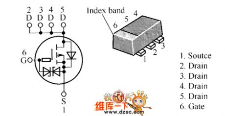
DMN5010VAK Internal Circuit
Published:2011/5/6 0:07:00 Author:Felicity | Keyword: Internal Circuit,
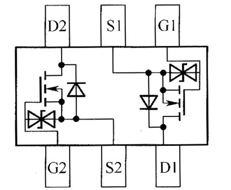
The picture above shows the DMN5010VAK Internal Circuit. (View)
View full Circuit Diagram | Comments | Reading(783)
Digit hygrometer circuit diagram composed of humidity sensitive capacitor
Published:2011/5/5 22:13:00 Author:Nicole | Keyword: digit hygrometer, humidity sensitive capacitor
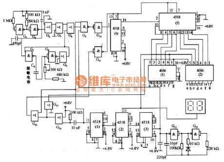
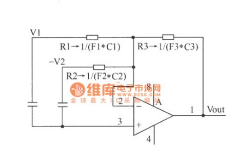
The figure1 is a digit hygrometer which is composed of humidity sensitive capacitor. 1KHz oscillator is made of G1, G2, it periodically trigger monostable trigger which is composed of G3, G4, the output pulse width is related to humidity sensitive capacitor. When the relative humidity is 0, the output pulse of monostable trigger is equal to oscillator's period; When the relative humidity is 100%, the output pulse width is 20% wider than it. The lasting time of G5-G8 XOR gates output humidity opposite pulse changes in relation to the humidity, the range is 0一100μs. In order to count the humidity opposite pulse, adding it and G12, G13, produced 200KHz narrow pusle to g9 input terminal, it produces narrow pusle only in the period of it has humidity opposite pulse. If it counts the humidity opposite pulse with 100μs maximum width and 50μs narrow pulse original sample, then the resolution is very low. So, it adds 200KHz oscillator's output pulse which is composed of G12, G13 to the input terminal of G9 and gate by 1Hz pulse singal of 4518(1)一4518(3) frequency division, it can obtain 500ms time.
G10's output pulse is displayed the measured relative humidity by 4518(4)和4518(5) frequency division and decoding driver to drive 2-bit display. G14一Gl6 transmissive pulse is used to reset the counter. (View)
View full Circuit Diagram | Comments | Reading(2134)
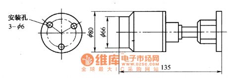
GY-YZ-161 high precision pressure sensor circuit
Published:2011/5/5 22:27:00 Author:Sharon | Keyword: high precision, pressure sensor
GY-YZ-161 high precision pressure sensor is made by use of semiconductor and micro-machining technology to combine solid-state integrated process technology with the isolating diaphragm.Its shape as shown in the figure.Pressure detection part is made by pressure-sensitive chip of high-precision and high stability, and processed by intensive temperature compensation and amplification, so as to make it more suitable for precision pressure test.GY-YZ-161 high precision pressure sensor is of high accuracy, high stability, high reliability and compatible with corrosive media, etc., and applicable to aerospace, weapons, ships and other fields. (View)
View full Circuit Diagram | Comments | Reading(1057)
UV sensor contour circuit
Published:2011/5/5 3:51:00 Author: | Keyword: UV sensor, contour
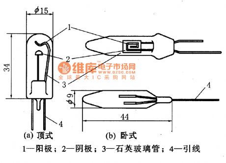
The structure of UV sensor is as shown in the picture. (a)the top structure, (b) the horizontal structure. In the quartz glass tube there are two electrodes, oneis the anode, the other is the cathode. A large quantity of special gas is sealed in the quartz glass tube. (View)
View full Circuit Diagram | Comments | Reading(1756)
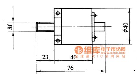
CZG-GD-500 series UV flame sensor contour circuit
Published:2011/5/5 2:15:00 Author: | Keyword: CZG-GD-500series, UV flame sensor, contour
CZG-GD-500 series UV flame sensor is made with ultraviolet phototube, which works as the sensing device and has the characteristics of high sensitivity, anti-interference ability and wide monitoring function. It's applicable to fire alarm systems in inflammable and explosive places, and also can be used for boilers, furnaces flame failure warning. Its dimensions are as shown in the picture. (View)
View full Circuit Diagram | Comments | Reading(1295)
Inductive proximity sensor operation circuit
Published:2011/5/5 2:14:00 Author: | Keyword: Inductive proximity sensor, operation
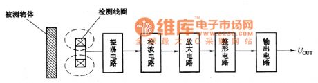
Inductive proximity sensor operation circuit
Proximity sensor is a kind of device which can perceive objects close to it . It uses sensibility of the displacement sensors to the objects nearby to identify objects and output switching signals. Therefore, proximity sensors are often referred to asproximity switches.
Inductive proximity sensor is a asproximity switch using vortex to percept objects . It consists of high-frequency oscillation circuit, detection circuit, amplifier, shaping circuit and output circuit, as shown in Figure 26-36. Perception sensor is as detection coil, which is an integral part of the oscillation circuit. In the work surface of the detection coil, there is an alternating magnetic field. When metal objects approach the detection coil, the metal objects will produce vortex and absorb the vibration energy, until vibration is reduced till to stop. And vibration and stop these two states will be output as switching signals.
(View)
View full Circuit Diagram | Comments | Reading(1855)
Phone With Musical Songs(I)Circuit
Published:2011/5/5 1:06:00 Author:chopper | Keyword: Phone, Musical Songs
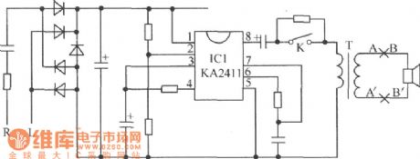
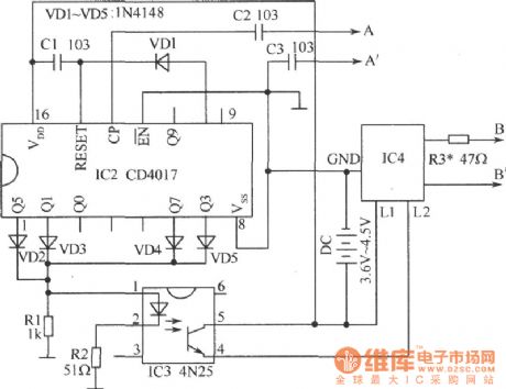
Now phoneshave the function of polyphonic ringtone and use various languages as well as songs instead of the traditional ringing,which makes people feel very novel.we can convert the monotonous ringing of home phone into songs with the chips in toy phone.The following picture is the ringing circuit of HA3288(22)P/TDL(LCD) SUBOR .In order to reduce the changes from the original circuit,unsolder two wires of loudspeaker in the ringing circuit merely.Entitle thesetwo wires A and A'.
Connect wires A and A'toGND through capacitorC2、C3 of the following circuit and the pin 14 of IC2.Entitle twobinding posts of the loudspeaker unsoldered B and B',and connect these two points to the corresponding point of IC4ofthe following picture.Picture below is the new ringingtrigger circuit.
(View)
View full Circuit Diagram | Comments | Reading(1273)
Camera Electronic Photometering System Circuit
Published:2011/5/4 22:52:00 Author:chopper | Keyword: Camera, Electronic, Photometering System
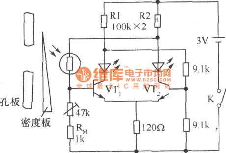
In the mid-range cameras,CdS photoresistor acts as aelectronic photometering component.When light reach the CdS photoresistor through the pore plate,move the density board to blance the circuit.And the even light sent out by two LEDs means optimum aeration.It meas underexposure or overexposure when one of the LEDs is brilliant while the other is dark.At this time,moving the density board would be a solution to get a optimum exposure. (View)
View full Circuit Diagram | Comments | Reading(808)
Brightness Control Relay Circuit
Published:2011/5/4 21:48:00 Author:chopper | Keyword: Brightness Control, Relay
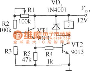
As shown in figure is a brightness control relay circuit.Resistance R1, R2 and photoresistance R3 form a divider circuit.When the light isdark to a certain degree,base voltage of VT1 increases,making the VT1 and VT2 connected,and relay J merged.R1 is used for sensibility control.The light-triggered pedestal of this circuit is influenced greatly by voltage and ambient temperature. (View)
View full Circuit Diagram | Comments | Reading(913)
Simple Light-operated Switch Circuit
Published:2011/5/4 4:02:00 Author:chopper | Keyword: Light-operated Switch
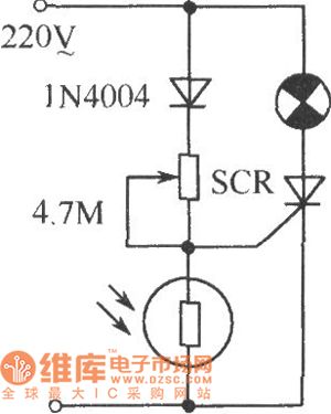
As shown in thefigure is a simple light-operated switch circuit.In some public places,it is convenient as well as power-saving whenapplied to,such as,passageway、street lamp...It starts automatically in the dark;and closes in the daytime.It is applicable to different types of photoresistance and opens under certain conditions(degree of darkness) by regulating 4.7 M Ω potentiometer.
(View)
View full Circuit Diagram | Comments | Reading(2269)
Bridge Photo-detectors of photoresistance Circuit
Published:2011/5/3 23:51:00 Author:chopper | Keyword: photoresistance, Bridge, Photo-detectors
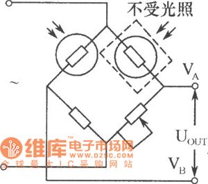
As shown in figure ,photoconductive resistance can form a bridge photo-detector in the industry photoelectric measuring device.Two of the same model (dark resistance equal) photoconductive resistanceact asbridge arms.One of them is used as photo-detectors;another sealed by black tape to avoid light as temperature compensation.This kind of Bridge Photo-detectors can use either dc or ac .When adopting ac modulation, it outputs for ac signal,which can reducenull shift of amplifier. (View)
View full Circuit Diagram | Comments | Reading(1089)
HAT1069C Internal Circuit
Published:2011/5/3 8:28:00 Author:Felicity | Keyword: Internal Circuit
The picture above shows the HAT1069C Internal Circuit. (View)
View full Circuit Diagram | Comments | Reading(827)
Digital hygrometer circuit diagram
Published:2011/5/3 2:20:00 Author:Ecco | Keyword: Digital, hygrometer
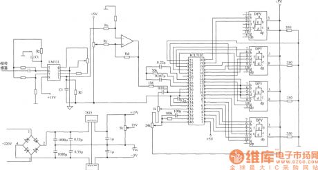
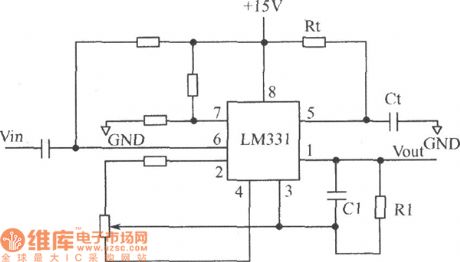
Digital hygrometer circuit mainly consists of the following parts: (1) humidity / voltage conversion circuit; (2) humidity / frequency conversion circuit; (3) the circuit composed of LM331; (4)display circuit.
(View)
View full Circuit Diagram | Comments | Reading(3783)
Brightness adjusting circuit diagram composed of LX1970 visible brightness sensor
Published:2011/5/2 22:15:00 Author:Ecco | Keyword: Brightness adjusting , visible brightness sensor
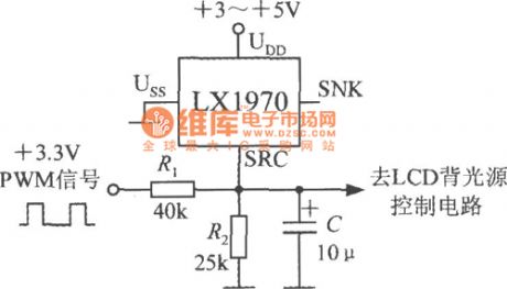
Brightness adjusting circuit is shown as the chart. Adjusting PWM (pulse width modulation) signal duty cycle, you can adjust the backlight brightness to suit individual needs. PWM signal voltage amplitude is 3.3V.
(View)
View full Circuit Diagram | Comments | Reading(834)
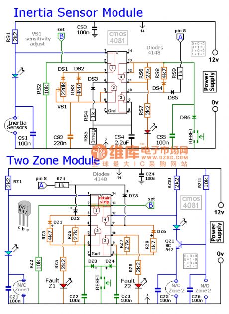
Inertial sensing module circuit diagram
Published:2011/5/2 22:04:00 Author:Ecco | Keyword: Inertial sensing module
View full Circuit Diagram | Comments | Reading(992)
| Pages:25/27 At 2021222324252627 |
Circuit Categories
power supply circuit
Amplifier Circuit
Basic Circuit
LED and Light Circuit
Sensor Circuit
Signal Processing
Electrical Equipment Circuit
Control Circuit
Remote Control Circuit
A/D-D/A Converter Circuit
Audio Circuit
Measuring and Test Circuit
Communication Circuit
Computer-Related Circuit
555 Circuit
Automotive Circuit
Repairing Circuit