
Sensor Circuit
Index 21
The computer connector LEV coupling circuit of photoelectric couplers
Published:2011/6/10 20:23:00 Author:qqtang | Keyword: computer connecto, LEV coupling circuit
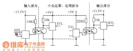
In computer systems, all kinds of semi-conductor logic circuits are connected with consciousness, and the different logic circuits requires different power supply voltages. Therefore, different logic circuits can be inter-connected, which is done after the LEV shifting, and it can be fulfilled by photoelectric couplers. For example, TTL integrated circuit characterizes fast speed and low price, etc, which is suitable for the computing part of the computer and the HTL circuit with high anti-disturbance, and it can normally work in the environment of high noise voltages. (View)
View full Circuit Diagram | Comments | Reading(994)
The switch circuit with two normally open contacts and closed contacts
Published:2011/6/10 20:33:00 Author:qqtang | Keyword: switch circuit, normally open contacts, closed contacts
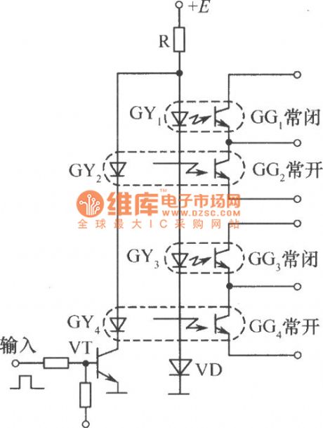
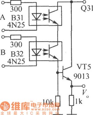
In the figure is the switch circuit with two normally open contacts and closed contacts, when the input signal is a low LEV 0 , the transistor TV is blocked, the LED GY2 and GY4 in the photoelectric couplers have no currents, and the light dependent triodes GG2 and GG4 are blocked, which is equal to the switch cutting off, we call them the normally open contact; however, when there are currents in GY1 and GY3, which makes GG1 and GG3 conducting, that is equal to switch closing, we call them the normally closed contact. When the input signals are high LEV 1 , the transistor VT is conducting. (View)
View full Circuit Diagram | Comments | Reading(1129)
The switch circuit with functions of self-lock (auto keeping) (1)
Published:2011/6/10 20:43:00 Author:qqtang | Keyword: switch circuit, self-lock
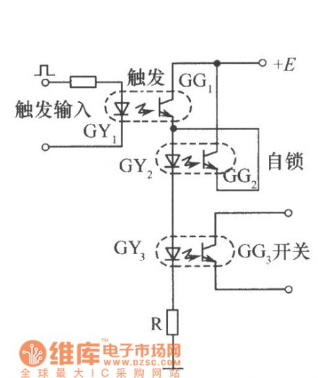
In the figure is a switch circuit with functions of self-lock (auto keeping). The 3 photoelectric couplers fulfill functions of trigger, self-lock and switch. When there are trigger signals on GYI, GG1 is conducting, GY2 and GY3 are glowing because of the currents in them, and GG2 and OG3 are conducting. When the trigger signals disappear, GY1 is put out and GG1 is blocked, but GG2 is conducting now, the currents of GY2 and GY3 are provided by GG2, GG3 remains in the conducting state, which is equal to switch going on conducting and the circuit won't recover until the power supply voltage E is gone. (View)
View full Circuit Diagram | Comments | Reading(1168)
The switch circuit with functions of self-lock (auto keeping) (2)
Published:2011/6/10 21:02:00 Author:qqtang | Keyword: switch circuit, self-lock
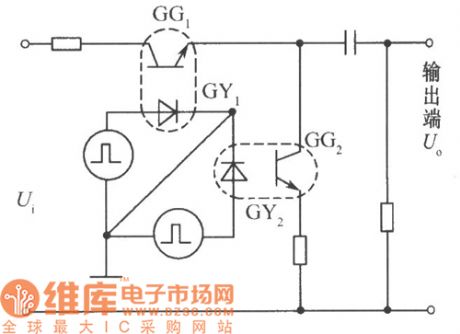
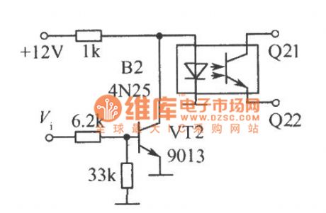
In the figure is the application in modulation (or wave chopper)of photoelectric couplers. Impose two square wave voltages, between which the difference is 180o, on GY1 and GY2 of the photoelectric coupler, so that they glow in turn, the light dependent triodes of GG1 and GG2 are conducting and blocked in turn, the output terminal gets periodical signals, which fulfills functions of modulation on the input signal Ui. (View)
View full Circuit Diagram | Comments | Reading(1383)
The simplest multi-oscillator circuit of photoelectric couplers
Published:2011/6/10 20:52:00 Author:qqtang | Keyword: multi-oscillator circuit, photoelectric couplers
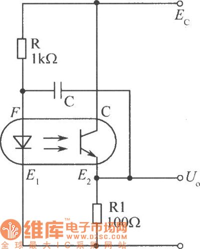
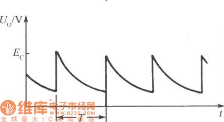
In the figure is simplest multi-oscillator circuit of photoelectric couplers. When the power is on, as the voltages on the two terminals of capacitor C can mutate and the resistance of resistor R is higher than RL, so the power supply voltage is mainly imposed on R, and the LEV on F is low, the LED is blocked, as the charging voltage of the capacitor increases, the LEV of F is rising. when the LEV rises to a certain value, the LED is conducting and glowing, the light dependent pipe is conducting, the output voltage is jumping and close to the voltage of the power supply.
(View)
View full Circuit Diagram | Comments | Reading(1117)
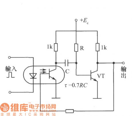
The single steady circuit of photoelectric couplers
Published:2011/6/10 21:03:00 Author:qqtang | Keyword: single steady circuit, photoelectric couplers
View full Circuit Diagram | Comments | Reading(897)
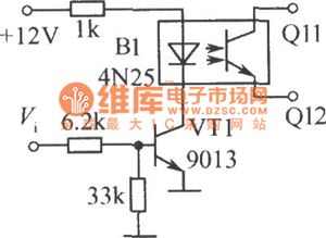
The high voltage steady circuit of photoelectric couplers
Published:2011/6/10 8:42:00 Author:qqtang | Keyword: high voltage, steady circuit, photoelectric couplers
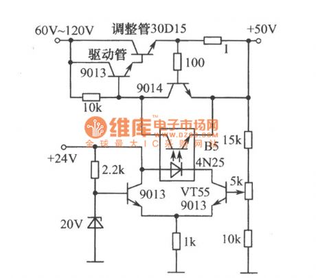
As is indicated in the figure, common drive pipes are high voltage transistors( in the figure, the drive pipe is 9013). When the output voltage increases, the bias voltage of VT55 is stepping up, which makes the positive current of the LED in B5 increase and the voltages between light dependent pipes reduce, and the bias voltage on the adjusting pipe reduces but the internal resistance increases, so the output voltage reduces; on the contrary, the output voltage steps up, so that the output voltage is kept steady. (View)
View full Circuit Diagram | Comments | Reading(951)
The auto light control circuit of photoelectric couplers
Published:2011/6/10 8:31:00 Author:qqtang | Keyword: control circuit, photoelectric couplers
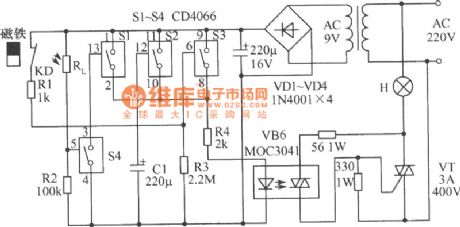
See as the circuit, in the 4 teams of analog electric switches(SI~S4), S1, S2 and S3 are in parallel connection, and they are used in the time delaying circuit, when they are connected with the power supply, they drive the dual-way transistor VT by R4 and VB6, VT directly control the hall lights; S4 and the external light dependent resistor RL form the outside ray detection circuit. When the door is closed, the closed type dry reed pipe KD, which is installed on the door frame, is affected by the magnet and it cut off, then S1, S2 and S3 are in open state. When the owner comes home at night, the magnet is away from KD, the KD touch spot is closed. (View)
View full Circuit Diagram | Comments | Reading(1412)
The connector circuit of photoelectric couplers
Published:2011/6/10 8:18:00 Author:qqtang | Keyword: connector circuit, photoelectric couplers
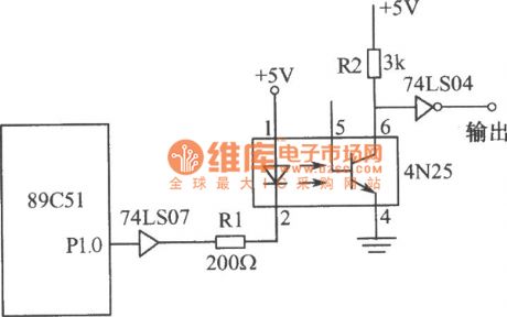
See as the circuit, the photoelectric coupler 4N25 performs the functions of coupling pulse signals and separating single chip computer 89C51 system from its output part, which makes the two parts separated. The output part of the ground wire connects with the shell and the earth, the power supply ground wire of 89C51 system is suspended, which is not connected with ground wire of the AC power supply, so that the power supply change of the output part has little effect on the single chip computer power supply, the effect on the small system is reduced, and the reliability of the system is increased. (View)
View full Circuit Diagram | Comments | Reading(1186)
The switch circuit of photoelectric couplers (2)
Published:2011/6/10 7:58:00 Author:qqtang | Keyword: switch circuit, photoelectric couplers
View full Circuit Diagram | Comments | Reading(906)
The AND gate logic circuit of photoelectric couplers
Published:2011/6/10 7:49:00 Author:qqtang | Keyword: AND gate, photoelectric couplers
View full Circuit Diagram | Comments | Reading(998)
The switch circuit of photoelectric couplers (1)
Published:2011/6/10 7:57:00 Author:qqtang | Keyword: switch circuit, photoelectric couplers
View full Circuit Diagram | Comments | Reading(933)
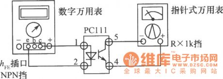
The digital multimeter test circuit of photoelectric coupler
Published:2011/6/10 7:55:00 Author:qqtang | Keyword: digital multimeter, photoelectric coupler
View full Circuit Diagram | Comments | Reading(867)
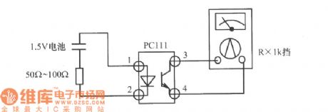
The effect judgement circuit of photoelectric couplers
Published:2011/6/10 7:52:00 Author:qqtang | Keyword: effect judgement, photoelectric couplers
View full Circuit Diagram | Comments | Reading(952)
The LEV display drive circuit of the TA7666P dual-line 5-bit LED
Published:2011/6/12 0:06:00 Author:qqtang | Keyword: LEV display, drive circuit
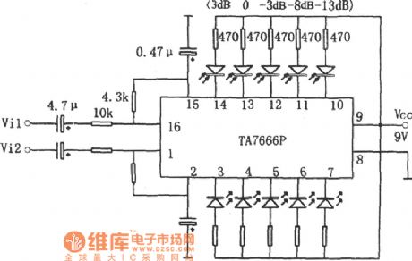
In the figure is the LEV display drive circuit of the TA7666P dual-line 5-bit LED. The integrated circuit of TA7666P is produced by Toshiba, the local products of TB7666P, XG7666P and so on are like it and can substitute it directly. (View)
View full Circuit Diagram | Comments | Reading(2962)
Touch switch circuit composed of the photoelectric coupler
Published:2011/6/8 4:05:00 Author:Christina | Keyword: Touch switch, photoelectric coupler
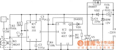
Working principle: The circuit which is composed of the capacitance C5, the regulator tube VDW, the diode VD2, the capacitance C4 and the resistance R6 can supply the 12V DC working voltage for the control part. When the hand touches the sheetmetal S, the neon tube N is ignited, the N and the photoconductive resistance RG form the photoelectric coupler, so at this time the resistance of RG becomes small, this makes the pin-2's electric potential of the integrated circuit 555 is lower than 1/3 of the power supply voltage, because of the NE555 was taken up into the monostable trigger, so the pin-3 of 555 sends out a positive pulse to the counting trigger port 14-pin of the integrated circuit, there is one count of the CD4017. (View)
View full Circuit Diagram | Comments | Reading(1649)
Outdoor antenna alarm circuit
Published:2011/6/8 4:05:00 Author:Christina | Keyword: Outdoor, antenna, alarm
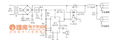
The outdoor antenna alarm circuit is as shown. The power supply of the microwave antenna is indoor, and the frequency converter is outdoor. They are connected with a 75 coaxial cable, this 75 coaxial cable is uses as the power cord and the signal line. In normal work, the current of 180mA~220mA gets through the electric cable, so we can form the alarm device by detecting this current and adding the simple alarm circuit. The current detection part is composed of the R1, R2, R3 and the photoelectric coupler IC1, the alarm device is composed of the NE555 and the peripheral components, the 7812 supplies the stable DC voltage for the 555. (View)
View full Circuit Diagram | Comments | Reading(1374)
Electric light touch switch circuit
Published:2011/6/8 3:37:00 Author:Christina | Keyword: Electric light, touch, switch circuit
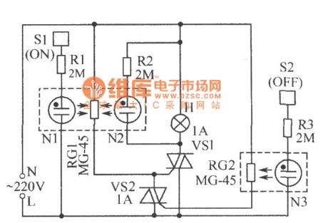
The circuit principle is as shown, the photoelectric coupler is composed of the neon tubes N1 and N2, the photoresistor RG1. When the hand touches the sheetmetal S1, the N1 turns on and the resistance of RG1 becomes small, so the two-way thyristor VS1 conducts because it gets enough trigger current, so the bulb H gets power to light. At the same time, the 220V AC voltage of H makes the N2 to light, this light is shining on the RG1, so at this time, even you stop touching, VS1 remains in the conduction state, and the H still lights. In the figure, the photoelectric coupler is composed of the neon tube N3 and the photoresistor RG2. (View)
View full Circuit Diagram | Comments | Reading(2225)
Light control timing switch circuit
Published:2011/6/8 7:11:00 Author:Christina | Keyword: Light control, timing, switch
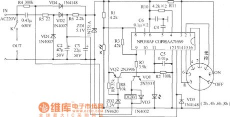
The Mexico light control timing switch circuit is as shown in the figure, this circuit can be used to control the outdoor lamps and the power supply of the advertisement lightbox, it is one kind of products that combined with the light control function and the gear shifting timing function, this circuit is very simple and easy to make. Turn the rotary switch to the timing gear of 2h, 4h, 6h or 8h, when there is no light, this circuit will automaticly control the corresponding time to reach the purposes of energy-saving and energy consumption reducing. (View)
View full Circuit Diagram | Comments | Reading(1138)
Money detector circuit
Published:2011/6/8 9:00:00 Author:Christina | Keyword: Money, detector
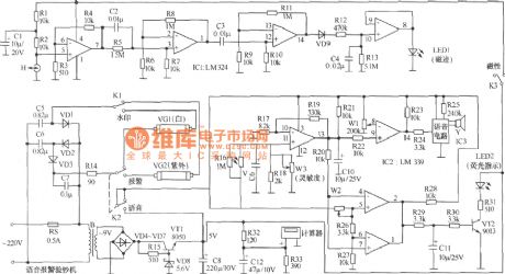
This voice alarm money detector circuit can be used to identify the counterfeit currency, it uses the sound of Please note that this is the counterfeit currency to remind the user, the internal circuit is as shown in the figure. It is composed of the magnetic trace detection circuit, the watermark detection circuit, the fluorescence instruction circuit, the power supply circuit and the voice alarm circuit.etc. (View)
View full Circuit Diagram | Comments | Reading(4463)
| Pages:21/27 At 2021222324252627 |
Circuit Categories
power supply circuit
Amplifier Circuit
Basic Circuit
LED and Light Circuit
Sensor Circuit
Signal Processing
Electrical Equipment Circuit
Control Circuit
Remote Control Circuit
A/D-D/A Converter Circuit
Audio Circuit
Measuring and Test Circuit
Communication Circuit
Computer-Related Circuit
555 Circuit
Automotive Circuit
Repairing Circuit