
Sensor Circuit
Index
ND specific sensor actual application circuit
Published:2014/4/15 22:41:00 Author:lynne | Keyword: ND specific sensor actual application circuit
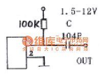
This is a solid state sensor is not sound control member, and when subjected to vibration or shaking greatly, its internal resistance will change quickly when added to the bias resistor R, a magnitude of the output voltage to the trigger signal, the signal Music can drive IC, control circuit, volume: 0.8 × 2 × 2.2cm, the application shown in Figure.
(View)
View full Circuit Diagram | Comments | Reading(3092)
Elastic strain sensor produced by household electronic scales circuit diagram
Published:2014/4/14 21:50:00 Author:lynne | Keyword: Elastic strain sensor produced by household electronic scales circuit diagram
This paper describes in electric scales, its basic principles and common spring scale similar to that of the spring is proportional to the weight of the object strain. However, it is structurally different from the ordinary spring balance, measurement instruction using electronic circuits. Electronics scale schematic is shown.
(View)
View full Circuit Diagram | Comments | Reading(2966)
Resistance strain type force sensor made of digital electronic circuit diagram
Published:2014/4/13 21:23:00 Author:lynne | Keyword: Resistance strain type force sensor made of digital electronic circuit diagram
The working principle
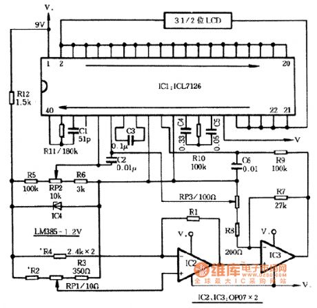
Digital electronic circuit principle as shown in figure, its main part is the resistance strain sensor R1 and IC2, consisting of the IC3 measurement amplifier circuit, and IC1 table and peripheral components of digital display panel. R1 sensor used on the ~ ZAA foil type resistance strain gauge, the normal value of 350 o. Measurement circuit will generate the resistance of the R1 variables should be converted into voltage signal output. The IC3 is the weak voltage signal is amplified and converted as A/D converter input analog voltage. IC4 provide l. 22 v voltage reference, it also the R5, R6 and RP2 after partial pressure for A/D converter reference voltage. 3-1/2 bits A/D converter ICL7126 reference voltage input end, introduced by contact among RP2, negative side is introduced by the middle of the RP3 contact. Reference voltage on both ends of nonlinear error of sensors suitable amount of compensation.
Component selection1. IC1 choose ICL7126 integrated block; IC2, the IC3 choose high precision low temperature standard precision op-amp OP - 07; IC4 choose LM385-1.2 V integrated block. 2. RI sensor selection on - ZAA foil type resistance strain gauge, the normal value for 350 o,. 3. The resistance element appropriate chooses precision metal film resistors. 4. RPI choose precision potentiometer, more RP2, RP3 after debugging respectively replaced with precision metal film resistors. 5. Capacitor C1 use mica or ceramic dielectric capacitors.
(View)
View full Circuit Diagram | Comments | Reading(2779)
Ordinary diode threshold gate circuit diagram
Published:2014/4/8 20:59:00 Author:lynne | Keyword: Ordinary diode threshold gate circuit diagram
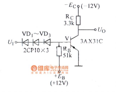
Ordinary diode threshold gate circuit diagram as shown:
(View)
View full Circuit Diagram | Comments | Reading(2281)
SF-10 module interface and temperature sensor circuit diagram
Published:2014/4/2 21:13:00 Author:lynne | Keyword: SF-10 module interface and temperature sensor circuit diagram
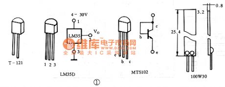
After the SF-10 Series Universal Control Module (Articles 1998 introduced the first one made) is available, a variety of upper and lower temperature controller design becomes very simple. In other words, just select the appropriate temperature sensor according to the control of the temperature range, according to the controlled object selection heater or cooling device, and then design temperature sensor and interface circuitry SF-10 on the line. This article describes some of the common temperature sensor interface circuit SF-10, and for the reader. Its shape and pin as shown.
(View)
View full Circuit Diagram | Comments | Reading(2968)
10-pin low-power digital temperature sensor circuit diagram
Published:2014/3/26 21:45:00 Author:lynne | Keyword: 10-pin low-power digital temperature sensor circuit diagram

AD7414, AD7415, AD7416, AD7814 and other four models, they work the same pinout as shown:
(View)
View full Circuit Diagram | Comments | Reading(3109)
MPX2100 pressure sensor and its application circuit diagram Ⅰ
Published:2014/3/26 21:37:00 Author:lynne | Keyword: MPX2100 pressure sensor and its application circuit diagram Ⅰ, MPX2100
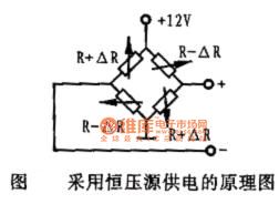
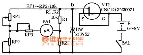
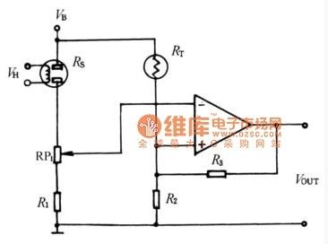
Works MPX2100 has four pins, between an output pin to ground, 3 feet plus working pressure, 2 feet and 4 feet and differential mode voltage signal proportional to the pressure. MPX2100 is a piezoresistive pressure sensor, made on a silicon substrate diffusion process four equal resistor strain elements constituting the Wheatstone bridge. Bridge has a constant voltage source and a constant current source power supply two power supply. Constant voltage source power supply schematic diagram shown in Fig.
When the pressure sensor is subjected to pressure, the resistance value of a bridge arm to increase ΔR, the other arm of the resistance value is reduced ΔR, the change of resistance ΔR proportional to the pressure, i.e. ΔR = KP, the bridge output voltage Uo = E (ΔR / R) = (EK / R) P, i.e., the bridge output voltage proportional to the pressure P.
(View)
View full Circuit Diagram | Comments | Reading(3180)
External buffer remote temperature measurement circuit diagram
Published:2014/3/25 21:31:00 Author:lynne | Keyword: External buffer remote temperature measurement circuit diagram,
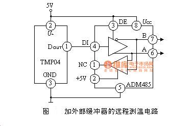
After the microcontroller coupled TMP03/04 easily microcomputer were measured in a counter t1, t2, then the software calculates the temperature. Because TMP03/04 is time ratio (t1/t2) to measure the temperature, so the computer does not require a very precise frequency counting, but counting frequency should be high enough.
(View)
View full Circuit Diagram | Comments | Reading(2031)
AS300 both ends of the integrated temperature sensor circuit diagram
Published:2014/3/25 21:29:00 Author:lynne | Keyword: AS300 both ends of the integrated temperature sensor circuit diagram, AS300
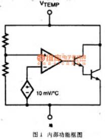
AS300 both ends of the integrated temperature sensor, is essentially a high-precision shunt regulator. Internal block diagram as shown. The output voltage proportional to the temperature sensor 27 ℃ when the output voltage is 3V, then the ratio of linear 10mV / ℃ increases. The sensor has a high accuracy, low output impedance, good linearity, etc., is an ideal device temperature detection.
AS300 There are four packages: TO-92, TO-237, SOT-223 packaged devices require larger heatsink. Using the TO-237 package, the device can be composed of ideal air temperature sensor. SOT-223 package uses the device is a hybrid substrate and the main MCM substrate temperature sensing devices. Such as requiring little installation space, high accuracy, the use of 8LSOIC package AS300 more suitable.
(View)
View full Circuit Diagram | Comments | Reading(1948)
Doppler effect sensor RD9481 application circuit diagram
Published:2014/3/24 21:32:00 Author:lynne | Keyword: Doppler effect sensor RD9481 application circuit diagram, RD9481
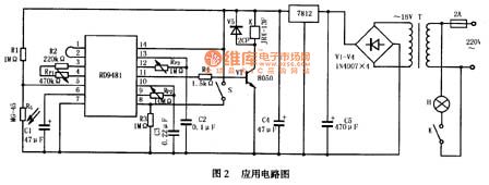
>Application Circuit
>RD9481R typical application circuit shown in Figure 2, the circuit is auto-sensing circuit lights, daytime lights are not bright, not bright at night when no one around, lights turn on automatically when someone walking.
After mains 220V transformer transformer, rectifier by (V1 ~ V4), the filter capacitor C4 and the voltage regulator circuit 7812 to get the DC supply voltage. RG photosensitive resistor R1 connected in series with the power supply voltage, the voltage divider circuit composed. During the day light shines onto the photosensitive resistor RG, RG showed low resistance, RD9481 5 feet low, blocking the trigger signal, the circuit does not work; night RG was high resistance, RD9481 5 feet high, so that the circuit to work . S is working mode selection switch, S is closed as a duplicate trigger work, S open to non-repeatable trigger work. Adjusting RP1, the sensitivity of the circuit can be adjusted to change the detection range can be adjusted to change the output high RP2 delay time adjustment block RP3 can change the timer has expired. (View)
View full Circuit Diagram | Comments | Reading(2968)
Gas sensor resistance with temperature schematic
Published:2014/3/18 21:22:00 Author:lynne | Keyword: Gas sensor resistance with temperature schematic,
Gas sensor resistance changes with temperature thermistor can be applied with similar characteristics to compensate for temperature. Figure 8-17 shows a bridge circuit connected to the gas sensor temperature compensation circuit, the circuit is also access to a comparator with hysteresis. Signal magnitude adjustment variable resistor RP1. When applied to the inverting input terminal of the voltage exceeds a threshold level of the upper limit, the output level is set at a low level. The reverse voltage is applied before the input level is lower than the threshold voltage, the high level of the output terminal is disposed, so as to significantly reduce the need for appropriate measurement when the concentration of gas.
(View)
View full Circuit Diagram | Comments | Reading(2391)
Using TC620 temperature sensor circuit diagram of computer room thermostat
Published:2014/3/16 21:07:00 Author:lynne | Keyword: Using TC620 temperature sensor circuit diagram of computer room thermostat, TC620
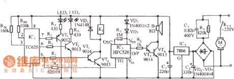
The circuit shown in FIG it by a temperature sensor, a control device, the minimum temperature of the display, the motor relay control circuit, the analog sound waves buck rectifier circuit and the AC circuit. (View)
View full Circuit Diagram | Comments | Reading(2776)
La1-xSrxFeO3,the equivalent circuit diagram of the transducer
Published:2014/3/9 21:34:00 Author:lynne | Keyword: La1-xSrxFeO3,the equivalent circuit diagram of the transducer, La1-xSrxFeO3
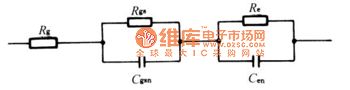
Figure: Rg-grain resistance, Rgs grain surface resistance, Cgsn grain surface non-Debye capacitive, Re-electrode surface resistance, Cen-electrode surface 'non Debye capacitor.
(View)
View full Circuit Diagram | Comments | Reading(1751)
Research sensor schematic circuit
Published:2014/3/6 20:57:00 Author:lynne | Keyword: Research sensor schematic circuit
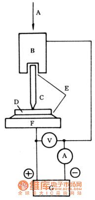
Figure: is a schematic diagram of Sensors A-adjustable pressure, B-metal needle electrode clamps, C-metal needle electrode, D-perovskite type oxide thin, E-or carbon-based conductive silver paste, F-metal a substrate, G-DC power supply.
(View)
View full Circuit Diagram | Comments | Reading(2174)
Nickel cadmium battery monitoring circuit diagram
Published:2014/2/27 20:19:00 Author: | Keyword: Nickel cadmium battery monitoring circuit diagram,
Nickel cadmium battery monitoring circuit diagram
(View)
View full Circuit Diagram | Comments | Reading(2411)
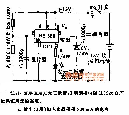
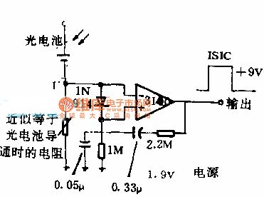
Light pulse receiving circuit diagram
Published:2014/2/27 20:15:00 Author: | Keyword: Light pulse receiving circuit diagram,
Light pulse receiving circuit diagram
(View)
View full Circuit Diagram | Comments | Reading(2782)
Tape fore and aft detector circuit diagram
Published:2014/2/26 20:21:00 Author: | Keyword: Tape fore and aft detector circuit diagram,
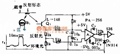
Tape fore and aft detector circuit diagram
(View)
View full Circuit Diagram | Comments | Reading(2124)
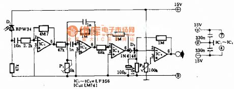
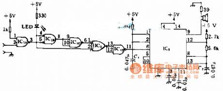
The light change detection circuit diagram
Published:2014/2/26 20:20:00 Author: | Keyword: The light change detection circuit diagram,
The light change detection circuit diagram
(View)
View full Circuit Diagram | Comments | Reading(2307)
Pulse frequency detection circuit diagram
Published:2014/2/25 21:19:00 Author: | Keyword: Pulse frequency detection circuit diagram,
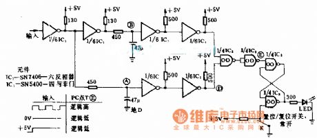
Pulse frequency detection circuit diagram
(View)
View full Circuit Diagram | Comments | Reading(2440)
Light and sound sensor circuit diagram
Published:2014/2/24 21:49:00 Author: | Keyword: Light and sound sensor circuit diagram,

Light and sound sensor circuit diagram
(View)
View full Circuit Diagram | Comments | Reading(2998)
| Pages:1/27 1234567891011121314151617181920Under 20 |
Circuit Categories
power supply circuit
Amplifier Circuit
Basic Circuit
LED and Light Circuit
Sensor Circuit
Signal Processing
Electrical Equipment Circuit
Control Circuit
Remote Control Circuit
A/D-D/A Converter Circuit
Audio Circuit
Measuring and Test Circuit
Communication Circuit
Computer-Related Circuit
555 Circuit
Automotive Circuit
Repairing Circuit