
Sensor Circuit
Index 13
bridge photoelectric detector composed of photosensitive resistor circuit
Published:2011/7/28 21:53:00 Author:John | Keyword: photosensitive resistor, bridge photoelectric detector
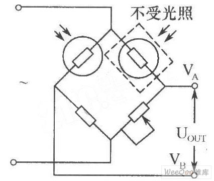
In the industrial optical measuring devices, the photosensitive resistor can be used to form the bridge photoelectric detector, just as shown in the figure. The two same models (with equivalent dark resistance) of the photoresistor are used as the bridge. One is for optical detection and the other is sealed with black tape. It is important to prevent it from being subjected to light as it is for temperature compensation. This type of bridge photodetector can be powered by DC or AC. When AC modulation, is used, its output is the AC signal, thus being able to reduce zero drift for the amplifier.
(View)
View full Circuit Diagram | Comments | Reading(1280)
THIRD_ELECTRODE_SENSES_FULL_CHARGE
Published:2009/6/29 21:13:00 Author:May
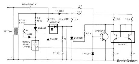
Circuit is suitable only for special nickel-cadmium batteries in which third electrode has been incorporated for use as end-of-charge indicator. Voltage change atthird electrode is sufficient to provide reliable shutoff signal for charger under all conditions of temperature and cell variations.-D. A. Zinder, Fast Charging Systems for Ni-Cd Batteries, Motorola, Phoenix, AZ, 1974, AN-447, p 7. (View)
View full Circuit Diagram | Comments | Reading(1193)
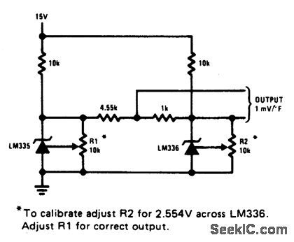
FAHRENHEIT_THERMOMETER
Published:2009/6/29 2:03:00 Author:May
View full Circuit Diagram | Comments | Reading(1098)
BASIC_DIGITAL_THERMOMETER_CELSIUS_AND_FAHRENHEIT_SCALES
Published:2009/6/29 2:02:00 Author:May
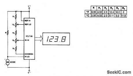
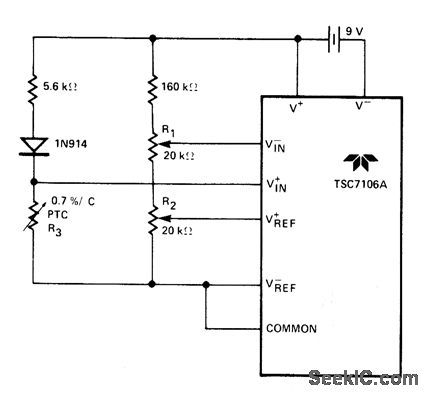
Maximum reading on the Celsius range is 199.9 ℃, limited by the (short-term) maximum allowable sensor temperature. Maximum reading on the Fahrenheit range is 199.9 °F (93.3 ℃), limited by the number of display digits. VREF for both scales is 500 mV. (View)
View full Circuit Diagram | Comments | Reading(1352)
POSITIVE_TEMPERATURE_SENSOR_COEFFICIENT_RESISTOR
Published:2009/6/29 2:00:00 Author:May
View full Circuit Diagram | Comments | Reading(1047)
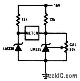
GROUND_REFERRED_CENTIGRADE_THERMOMETER_1
Published:2009/6/29 1:59:00 Author:May
View full Circuit Diagram | Comments | Reading(1914)
TEMPERATURE_SENSOR_1
Published:2009/6/29 1:58:00 Author:May
View full Circuit Diagram | Comments | Reading(1021)
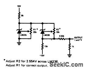
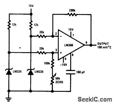
GROUND_REFERRED_CENTIGRADE_THERMOMETER
Published:2009/6/29 1:57:00 Author:May
View full Circuit Diagram | Comments | Reading(932)
GROUND_REFERRED_FAHRENHEIT_THERMOMETER
Published:2009/6/29 1:55:00 Author:May
View full Circuit Diagram | Comments | Reading(1123)
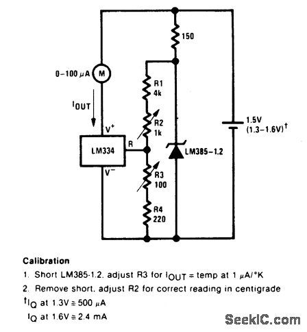
0℃_100℃_THERMOMETER
Published:2009/6/29 1:55:00 Author:May
View full Circuit Diagram | Comments | Reading(826)
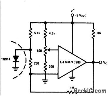
TEMPERATURE_TO_FREQUENCY_CONVERTER
Published:2009/6/29 1:52:00 Author:May
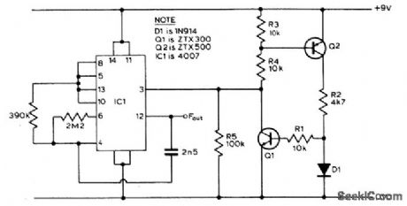
The circuit exploits the fact that when fed from a constant current source, the forward voltage of a silicon diode varies with temperature in a reasonably linear way. Diode D1 and resistor R2 form a potential divider fed from the constant current source. As the temperature rises, the forward voltage of D1 falls tending to turn Q1 off. The output voltage from Q1 will thus rise, and this is used as the control voltage for the CMOS VCO. With the values shown, the device gave an increase ofjust under 3 Hz/℃ (between 0 ℃ and 60 ℃) giving a frequency of 470 Hz at 0 ℃. (View)
View full Circuit Diagram | Comments | Reading(0)
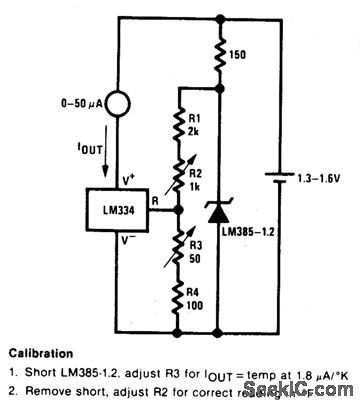
0°F_50°F_THERMOMETER
Published:2009/6/29 1:49:00 Author:May
View full Circuit Diagram | Comments | Reading(853)
LOWER_POWER_THERMOMETER
Published:2009/6/29 1:48:00 Author:May
View full Circuit Diagram | Comments | Reading(958)
CENTIGTADE_THERMOEETER
Published:2009/6/29 1:47:00 Author:May
View full Circuit Diagram | Comments | Reading(1018)
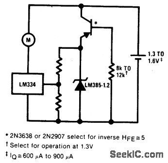
KELVIN_THERMOMETER_WITH_GROUND_REFERRED_OUTPUT
Published:2009/6/29 1:46:00 Author:May
View full Circuit Diagram | Comments | Reading(995)
DIFFERENTIAL_TEMPERATURE_SENSOR
Published:2009/6/29 1:44:00 Author:May
View full Circuit Diagram | Comments | Reading(0)
SIMPLE_DIFFERNTIAL_TEMPERATURE_SENSOR
Published:2009/6/29 1:42:00 Author:May
View full Circuit Diagram | Comments | Reading(892)
REMOTE_TEMPERATURE_SENSING
Published:2009/6/29 1:39:00 Author:May
View full Circuit Diagram | Comments | Reading(0)
BASIC_DIGITAL_THERMOMETER_KELVIN_SCALE_WITH_ZERO_ADJUST
Published:2009/6/29 1:35:00 Author:May
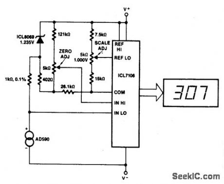
This circuit allows zero adjustment as well as slope adjustment. The ICL8069 brings the input within the common-mode range, while the 5 K pots trim any offset at 218 °K (-55 ℃), and set scale factor. (View)
View full Circuit Diagram | Comments | Reading(1104)
BASIC_DIGITAL_THERMOMETER_KELVIN_SCALE
Published:2009/6/29 1:30:00 Author:May
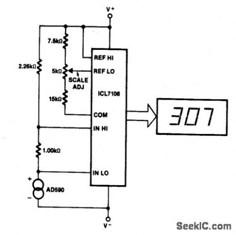
The Kelvin scale vers1on reads from0 to 1999°K theoretically,and from 99Q°K to 473°K actually. The 2.26 K resistor brings themput within the ICL7106 VCM range∶twogeneral-purpose silicon diodes or an LED maybe subsituted. (View)
View full Circuit Diagram | Comments | Reading(1079)
| Pages:13/27 1234567891011121314151617181920Under 20 |
Circuit Categories
power supply circuit
Amplifier Circuit
Basic Circuit
LED and Light Circuit
Sensor Circuit
Signal Processing
Electrical Equipment Circuit
Control Circuit
Remote Control Circuit
A/D-D/A Converter Circuit
Audio Circuit
Measuring and Test Circuit
Communication Circuit
Computer-Related Circuit
555 Circuit
Automotive Circuit
Repairing Circuit