
Sensor Circuit
Index 3
Automatic Street Lights Intensity Control Project
Published:2013/9/17 20:12:00 Author:lynne | Keyword: Automatic Street Lights Intensity Control Project
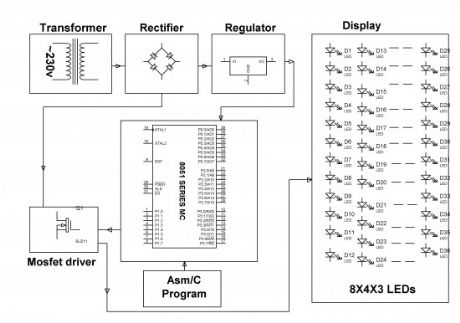
White LED (Light Emitting Diodes) substitutes HID lanterns in road illumination system to add on dim element. 8051 family’s micro-controller is bring into play to control the power by growing pulse width transformed pointers that impels a MOSFET to swap the Light Emitting Diodes accordingly to accomplish most wanted function.
In the current system, maximum lightning over the freeways is completed through HID (High Intensity Discharge lamps), the energy utilization of HID lamps/lanterns are high. The intensity of HID lamps cannot be controlled, in harmony to the necessity, therefore there is a requirement to swap to a substitute way of illumination system i.e., by making use of LEDs. This lighting system is constructed to conquer the disadvantages of High Intensity Discharge lamps.
This lightning system exhibits the utilization of the Light emitting diodes or LED’s as the source of light and its intensity control is variable which can be altered as per the requirement. LED’s use a lesser amount of power and its life span is good, in comparison to the old HID lanterns/lamps. The more vital and motivating characteristic is that the intensity of LED’s can be controlled as per the requirement throughout non-peak hours which is not possible with HID lanterns/lamps.
A bunch of LEDs are brought into play to structure a street light. The micro-controller includes planned instructions which are used for controlling the intensity of lanterns based on Pulse width modulation (PWM) produced indicators. The lights intensity are kept soaring all through the peak hours, because the street traffic have a propensity to reduce slowly during late night hours, the intensity of the traffic also declines gradually till sunrise. Finally it’s totally shuts down at dawn, and it’s all over again restarts at 6pm during the dusk. The course of action is repeated.
(View)
View full Circuit Diagram | Comments | Reading(1967)
LED Security Light with PIR Motion Sensor Circuit
Published:2013/9/9 20:24:00 Author:lynne | Keyword: LED Security Light with PIR Motion Sensor Circuit
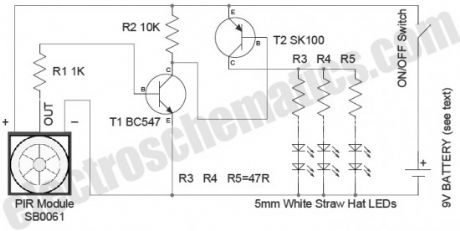
In this security light circuit, High level (3.3V) output from SB0061 is used to switch on six 5mm white straw hat LEDs through a solid-state switch realized using transistors T1 & T2. PIR sensor modules usually have a 3-pin connection: Vcc (+) , Output, and Ground (-) . The pinout may vary, so it is recommend to check the manufacturer’s datasheet to confirm the pins. Besides PIR sensor module also has a 3-pin jumper selection for single or continuous trigger output mode.
The two positions have labels H and L. When the jumper is at H position, the output remains high when the sensor is re-triggered repeatedly. In position L, the output goes high and low every time the sensor is triggered. So a continuous motion will give repeated high/low pulses in this mode.
The PIR LED light security circuit can be powered from a compact 9V rechargeable battery. Note that the battery charger circuit is not included with the circuit schematic. You can use any suitable external 9V battery charger to re-charge the battery pack.
(View)
View full Circuit Diagram | Comments | Reading(2740)
Dim 12V Light Bulb with 555 IC
Published:2013/8/26 1:23:00 Author:lynne | Keyword: Dim 12V Light Bulb with 555 IC
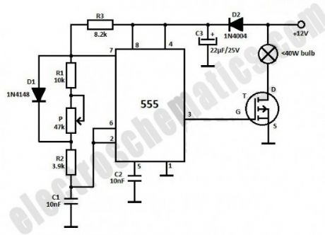
This light dimmer is used to dim the intensity of 12V light bulbs using the well-known 555 timer that is configured as an astable multivibrator. The pulses from pin 3 are used to control the VMOS transistor BUZ20, BUZ72 or 10N10. The maximum dissipated power must not exceed 40 watts. You may use the transistor without a heatsink if the power does not exceed 10 watts.The 555 IC powering is done through D2 diode and is filtered using C3 capacitor. The resistors can be 0.25W or 0.5W with a tolerance of ±5%.
(View)
View full Circuit Diagram | Comments | Reading(2602)
Low Cost Door Sensor
Published:2013/8/8 20:19:00 Author:lynne | Keyword: Low Cost Door Sensor
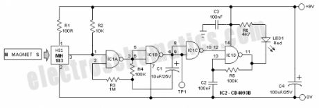
At the heart of the circuit is one Unipolar Hall effect sensor MH183 (HS1). It incorporates advanced chopper stabilization technology to provide accurate and stable magnetic switch points. The internal output transistor of MH183 will be switched on in the presence of a sufficiently strong South pole magnetic field facing the marked side of the package. Similarly, the output will be switched off in the presence of a weaker South field and remain off with “0” field. A Hall-effect sensor IC (contactless & magnetically activated) is more efficient and effective than reed, inductive or opto-electronic sensors, and is virtually immune to environmental contaminants.
(View)
View full Circuit Diagram | Comments | Reading(2134)
Capacitive Sensors
Published:2013/7/29 20:24:00 Author:muriel | Keyword: Capacitive Sensors
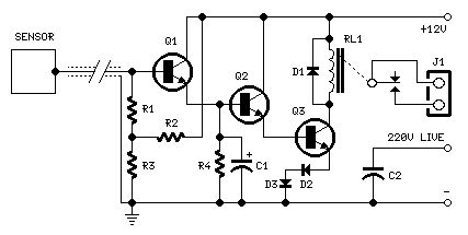
Parts:R1,R2 1M 1/4W ResistorsR3,R4 47K 1/4W ResistorsC1 10µF 25V Electrolytic CapacitorC2 470pF 630V Ceramic or Polyester CapacitorD1-D3 1N4002 100V 1A DiodesQ1-Q3 BC337 45V 800mA NPN TransistorsRL1 Relay with SPDT 2A @ 220V switchCoil Voltage 12V. Coil resistance 200-300 OhmJ1 Two ways output socketSensor Aluminium or copper thin sheet with the dimensions of a post-card,glued at the rear of the same (approx. 15x10.5 cm.)Thin screened cable
Circuit description:The purpose of this circuit is to animate shop-windows by means of a capacitive sensor placed behind a post-card-like banner. The card is placed against the glass inside the shop-window, and the visitor can activate the relay placing his hand on the card, from the outside. Especially suited for toy-shops, the circuit can activate model trains, small electric racing cars, lights etc. Further applications are left at user's imagination. Adopt it to increase the impact of your shop-window on next Christmas season!Q1, Q2 & Q3 form a high impedance super-Darlington that drives the relay, amplifying the 50Hz alternate mains-supply frequency induced in the sensor by the human body. C1 & D2, D3 ensure a clean relay's switching. Power supply can be any commercial wall plug-in transformer with rectifier and smoothing capacitor, capable of supplying the voltage and current necessary to power the relay you intend to use. (View)
View full Circuit Diagram | Comments | Reading(1963)
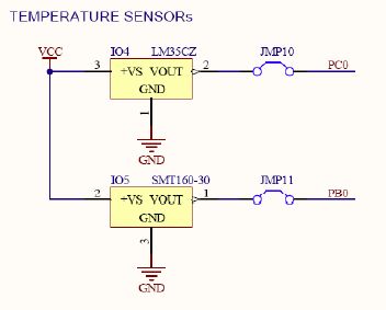
temperature sensors
Published:2013/7/9 3:17:00 Author:muriel | Keyword: temperature sensors
View full Circuit Diagram | Comments | Reading(1340)
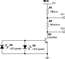
Alternate LED4 Sensor Schematic
Published:2013/7/5 1:51:00 Author:muriel | Keyword: Alternate, LED4 , Sensor Schematic
View full Circuit Diagram | Comments | Reading(1322)
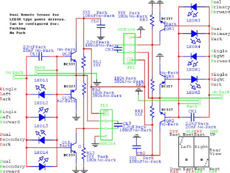
LED3X Remote Sensor
Published:2013/7/5 1:49:00 Author:muriel | Keyword: LED3X , Remote Sensor
View full Circuit Diagram | Comments | Reading(1170)
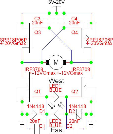
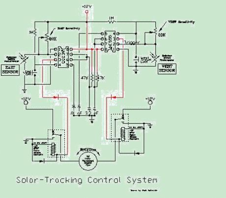
Bidirectional Analog Solar Tracker or Sensor
Published:2013/7/5 1:46:00 Author:muriel | Keyword: Bidirectional Analog, Solar , Tracker, Sensor
View full Circuit Diagram | Comments | Reading(3298)
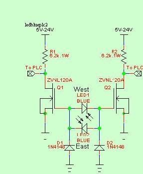
Another Sensor for use with a PLC 2
Published:2013/7/5 1:40:00 Author:muriel | Keyword: Another Sensor, PLC
View full Circuit Diagram | Comments | Reading(915)
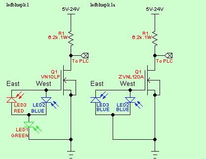
Another Sensor for use with a PLC
Published:2013/7/5 1:39:00 Author:muriel | Keyword: Another Sensor , PLC
View full Circuit Diagram | Comments | Reading(1062)
Light sensors
Published:2013/7/5 1:33:00 Author:muriel | Keyword: Light sensors
View full Circuit Diagram | Comments | Reading(1345)
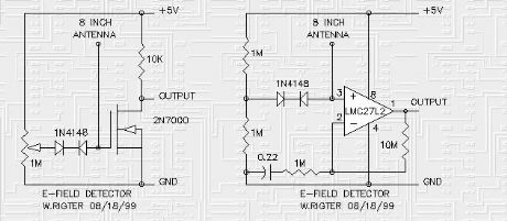
Field (electric, capacitance) sensors
Published:2013/7/3 2:28:00 Author:muriel | Keyword: Field (electric, capacitance) sensors
View full Circuit Diagram | Comments | Reading(1581)
Multiple Sensors
Published:2013/6/6 20:33:00 Author:muriel | Keyword: Multiple Sensors
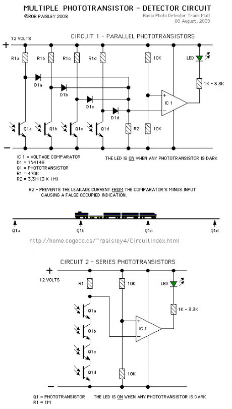
More than one phototransitor can be connected to a single voltage comparator. This would allow transistors to be placed along a section of track to indicate when a train is anywhere in that section.
As long as the train is long enough to cover two sensors the circuit will continuously detect the train.
(View)
View full Circuit Diagram | Comments | Reading(1517)
Deer Repellent/ Seismic Sensor 2
Published:2013/5/14 22:06:00 Author:muriel | Keyword: Deer Repellent/ Seismic Sensor

View full Circuit Diagram | Comments | Reading(1577)
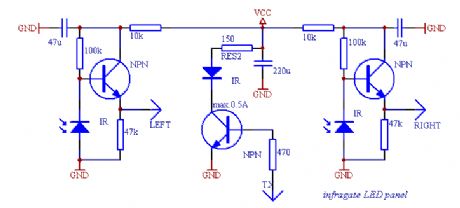
Infrared gate sensor
Published:2013/4/18 1:54:00 Author:muriel | Keyword: Infrared gate, sensor

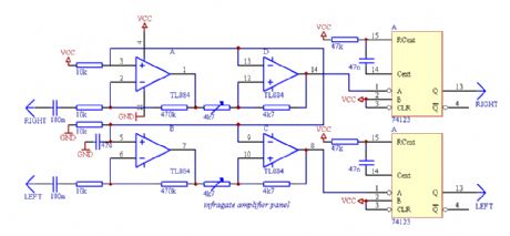
This is an infrared gate with two sensors planned to use in the wall in the way behind a door. It can be applied in a toilet to keep track of that someone is inside exceeding a certain amount of time. After that time elapsed, the circuit triggers the digital output wich can turn on a ventillator. The time period the output is turned on can be separately controlled by a second timer.
If you plan to build this circuit, beware that you may have lots of difficulties though the schematic may seem simple. The construction of the circit requires some amount of equipment like an oscilloscope and a DVM, too. Without them, the device will do weird things you wouldn't expect, and even if it is correctly put together, you must adjust it with care both mechanically in its final place and electronically with the help of an oscilloscope. Only if you want to span about less than 20-30 inches with the infra diodes can forget about this calibration. Alternatively you can take ideas from this construction.
The device consists of several parts, the most critical one is the panel with the infra LEDs. I tried to use several receiver transistors, but best result was given by infra receiver diodes used in TV remote control receivers. The receiver diodes must be properly shielded from the transmitter LED(s) otherwise the infra light will surely drive the receiver with a large enough signal. These photodiodes should only see infrared light coming from the mirror. The two very sensitive receiver parts should also be isolated from the transmitter electrically or the TX signal will get across the wires to the RX lines, which results the same effect as weak optical shielding. Use metal shielding around the receiver amplifiers where possible. The infrared transmitter LEDs should be close in wavelength to the max. sensitivity band of the receivers. You can experiment with using more LEDs and more current testing several resistor values, but don't exceed the 500 mA current limit flowing on the diodes or they will burn out. Do not shield the transmitters, allow the maximum amount of infralight to reach the mirror to extend the possible range.
Update: The TTL IC called '74123' is actually a 74HC123, and is used out of the specifications - although it is rated up to 7VDC supply voltage as absolute maximum, in this project it is powered from VCC=9-12VDC without problems. I am ashamed of neglecting such an important aspect.
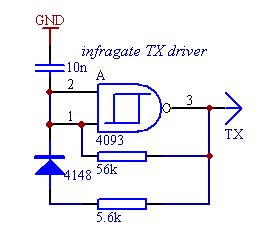
To start testing the infra LED panel, you wil need the infragate amplifier panel and the small transmiter driver. The TX driver will generate the digital signal for the LED driver on the LED panel. The digital signal is 1:10 on/off to achive good performance with lower power dissipation on the LEDs. Connect GND, VCC planes and LEFT, RIGHT wires of the LED panel with the amplifier panel, and drive the TX line from the TX driver. Now you are able to start testing and calibrating the analogue part of the circuit. If everything is ok, holding a mirror in front of the LED panel will reflect enough signal to overdrive the amplifier and you can check the output on the OPA 1, 7 pins with an oscilloscope. Taking the mirror farther on will result a weakening signal on the amplifier output. Set the orientation of the diodes to be able to get the maximum signal amplitude on the oscilloscope screen. This is the heaviest part of the work, don't deal too much with it until the complete circuit is not built. Just adjust a static state of the construction to give the maximum signal amplitude on the output when nothing is between the diodes and the mirror and give a small noise only when the line of sight is covered. If you are ready with it, you can adjust the schmitt triggers built of the other two OPA parts to generate TTL pulses when the analog signal is at its maximum and stay on the same DC level when the received signal is missing.
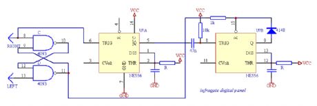
It is also important to protect the receiver diodes from direct light as natural light will weaken the sensitivity of the diodes, and lamps will transform the 50/60 Hz modulation present in the line power. Small noise is not problem, but the received signal from the TX generator should be stronger to be able to detect it. After the ST adjustments, connect LEDs to the 74123's TTL outputs through proper value resistors. The 74123 here is used as a demodulator. If there is a periodic signal change on the input, the output will be high, while if there is no activity on the input for a given period of time, the output falls low. When you cover the line of sight of one receiver diode, the corresponding LED turns off. There should not be any flickering in the turning on/off, the output should immediately respond to the change without blinking.
If still everything is correctly working at this point, the remaining digital circuit is the easy part of the work. The outputs of the previous circuit (LEFT, RIGHT) directly connect to the remaining part. The RS memory built from two NAND gates remembers the way of the last movement direction, so if someone is in or not. If you experience problems, connect another LED to pin 10 of the RS and check if this part does what it should. If there was any activity in the past minutes, the first timer is running, but it can only trigger the second timer part, if someone is still inside. The diode from the second timer output prevents resetting itself before the timing period is over in case of another movement. For a 1 minute timing (first timer) R=470k C=100u can be used, the second part would use R=1.5M C=470u for about a 15 minute timing (t=1.1RC). The output of the second timer (pin 9) can drive a relay activating the ventillator.
(View)
View full Circuit Diagram | Comments | Reading(2232)
One Direction Motion Sensor circuit
Published:2013/3/28 4:08:00 Author:Ecco | Keyword: One Direction Motion , Sensor
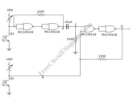
This is a one direction motion sensor circuit. This motion sensor circuit is used to detects an object passing in one direction, ignoring an object that going to opposite way. This circuit uses two sensors to identify the movement only in one direction. The basic principle of this circuit is simple, where one sensor is used to generate a short pulse, and the other sensor is used to block of turn of the gate. The phototransitors give high output on their collectors when there is an object blocking the light. By a 0.4uF differentiator capacitor, the interruption of light at Q2 sensor will produce short pulse at point C. But this short pulse will only appear at the output if a high signal appears at A. This condition will be satisfied if the light to Q1 is blocked by the object when the object is passing through Q2, means that the direction should be from Q1 to Q2. Here is the schematic diagram of the circuit:
(View)
View full Circuit Diagram | Comments | Reading(2060)
LPG Gas Leakage Sensor Alarm
Published:2013/3/25 4:03:00 Author:Ecco | Keyword: LPG Gas Leakage, Sensor, Alarm
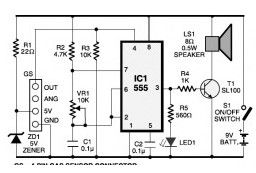
This is the schematic diagram of LPG gas leakage sensor alarm. The circuit operates off a 9V PP3 battery. Zener diode ZD1 is applied to convert 9V into 5V DC to drive the gas sensor module. The SEN-1327 gas sensor module from RhydoLABZ is applied in this circuit. Its output goes higher when the gas amount reaches or exceeds specific point.
(View)
View full Circuit Diagram | Comments | Reading(2103)
Constant Temperature Circuit
Published:2013/3/10 23:05:00 Author:Ecco | Keyword: Constant Temperature

The 7805 voltage regulator provides a reference voltage that is fed into a resistive bridge formed on one side by the 20K trimmer and the other side by the 3.3K resistor and the 1K/thermistor combination. The termistor is an NTC (Negative Temperature Coefficient) type. The op-amp is run in a differential mode and tries to keep its inputs at the same potential by the thermal feedback loop formed by the heater and the thermistor.
The three 1N4001 diodes are used to bias the emitter of the transistor up enough that it can shut off fully with the limited voltage swing from the 741 op-amp. The heating indicator LED (a standard red LED) also taps off of the same diode ladder to enable it to shut off entirely.
The value of the (1uF) capacitor in the op-amp feedback loop may need to be adjusted if the circuit rings , or swings back and forth before stabilizing on a temperature. The capacitor value is specific to the thermal mass that is being temperature stabilized.
The heater resistor is rated at approximately 40 ohms and 5 watts. The value of the resistor determines the heating rate and the power consumption. The resistor value should not be too low or the resulting high current will damage the 1N4001 diodes and/or the TIP122 transistor.
(View)
View full Circuit Diagram | Comments | Reading(1700)
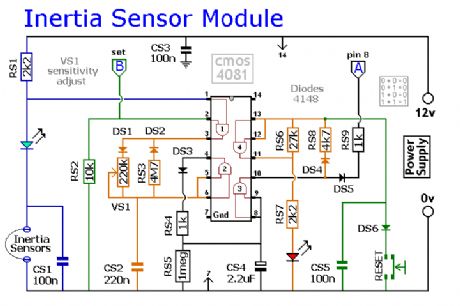
Inertia-Sensor Module
Published:2013/2/1 20:13:00 Author:muriel | Keyword: Inertia-Sensor Module
View full Circuit Diagram | Comments | Reading(1983)
| Pages:3/27 1234567891011121314151617181920Under 20 |
Circuit Categories
power supply circuit
Amplifier Circuit
Basic Circuit
LED and Light Circuit
Sensor Circuit
Signal Processing
Electrical Equipment Circuit
Control Circuit
Remote Control Circuit
A/D-D/A Converter Circuit
Audio Circuit
Measuring and Test Circuit
Communication Circuit
Computer-Related Circuit
555 Circuit
Automotive Circuit
Repairing Circuit