
Sensor Circuit
Index 6
Temperature system analog circuit for Resistance temperature detector
Published:2011/9/9 2:59:00 Author:John | Keyword: Temperature system analog circuit, Resistance temperature detector
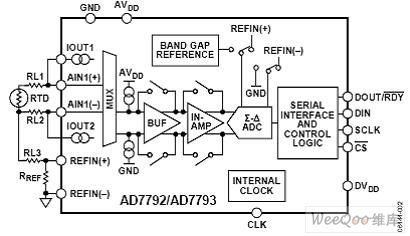
The resistance of resistance temperature detector changes as the temperature changes. Commonly used materials for resistance temperature detectors are nickel, copper and platinum. And the platinum resistance temperature detector of 100 Ω~1000 Ω is the most common type. Resistance temperature detectors are suitable for linear response of temperature measurement within -200 ° C to +800 ° C. A resistance temperature detector includes three or four wires. Figure 2 shows the connection diagram for 3-wire resistance temperature detector and the analog converter. And RL1, RL2 and RL3 respectively represent the wire’s resistance for resistance temperature detector. (View)
View full Circuit Diagram | Comments | Reading(1497)
The digital telemetering thermometers FDD5 and JDD5
Published:2011/9/4 20:34:00 Author:TaoXi | Keyword: Digital telemetering thermometer
Transmitter circuit:
The temperature detecting circuit is composed of the temperature integrated sensor AD590, this circuit changes the temperature variation into the output current variation. AD590's output current is proportional to the measurement temperature, as the temperature increases, the output current increases with the 1μA/K constant ratio. When the output current gets through RP2, at the top of RP2 forms the voltage, and this voltage is amplified by the voltage amplifier and is used as the voltage-frequency changer's control voltage.
Receiving circuit:
(View)
View full Circuit Diagram | Comments | Reading(1119)
Photoelectric Encoder Phase Counting Circuit
Published:2011/5/17 3:03:00 Author:Sharon | Keyword: Photoelectric Encoder, Phase Counting
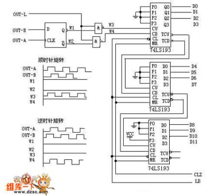
When the photoelectric encoder rotates clockwise, the channel A is ahead of Channel B 90°by output waveform. D flip-flop output Q (waveform W1) is high, and Q (waveform W2) is low.The top nonconjunction gate is open, and the counting pulses pass through (waveform W3), and then are sent to bi-directional counter 74LS193's plus pulse inputs CU for the addition count; At this point, the bottom nonconjunction gate is closed, the output is high(waveform W4). When the photoelectric encoder rotates counter-clockwise, channel A legs behind Channel B 90°in output waveform. D flip-flop output Q (waveform W1) is low, and Q (waveform W2) is high. The top nonconjunction gate is closed, and the output is high (waveform W3); At this point, the bottom nonconjunction gate is open, counting pulses get through (waveform W4), and are sent to decrease pulse input CD of the two-way counter 74LS193 CD for the subtraction count. (View)
View full Circuit Diagram | Comments | Reading(3094)
Incremental Photoelectric Encoder Basic Waveforms and Circuit
Published:2011/5/17 2:38:00 Author:Sharon | Keyword: Incremental, Photoelectric Encoder, Basic Waveforms
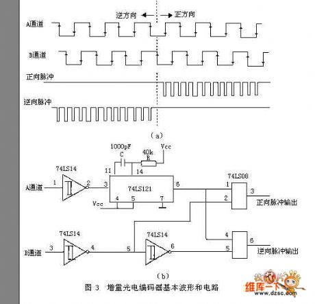
Incremental encoder is a sensor output pulse. Its encoder disk and resolution is much simpler and higher than those of the absolute encoder. Usually it only requires three code channels, where the code channels actually do not have the absolute meaning of the encoder code channel, but form the count pulse.Its encode disk external and middle channel have the same number of average-distributed transparent or no-transparent fan-shaped area (raster), and the two fan-shaped areas are separated by half-area. When the decode disc rotates, the output signal is pulse signal with 90 °phase shift of the A phase and B phase. And pulse signal has only a light slit produced by the third code channel (It acts as a basis of encoder disk and provides an initial zero signal for count).
The phase relationship of A and B two output signals (lead or lag) can determine the direction of rotation. Figure 3 (a) shows when the encoder disk rotates forward, A channel's pulse waveform is advanced than that of B channel by π / 2, while in reversal, A channel's pulse waveform legs behind that of B channel by π / 2. Figure 3 (b) is a real circuit, with the bottom of A channel's shaping wave triggering the monostable and generating positive pulse, and then touching with B channel's shaping wave. When the encoder disk rotates forward, only positive pulse outputs, otherwise, only the reverse pulse outputs.
(View)
View full Circuit Diagram | Comments | Reading(4575)
object motion path distinguishmen circuit
Published:2011/9/6 23:44:00 Author:chopper | Keyword: motion path, distinguishmen circuit
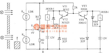
Puttwo photoresistors who have the similar resistance and performance on the same side of the object motion path at theappropriate distance.Settwo light sourceson the relative position of the other side respectively, so that objects can move in a straight line between the light source and photosensitive resistor. Using the circuit shown in picturecan determine the direction of motion path. Circuit is formed by the bridge and polarity distinguishment. Rs1, Rs2, R1, R2, and Rw form the bridge and power supply E0 offers the power,and endsA, B output. (View)
View full Circuit Diagram | Comments | Reading(1722)
precise optical control circuit
Published:2011/8/25 20:54:00 Author:chopper | Keyword: optical, control circuit
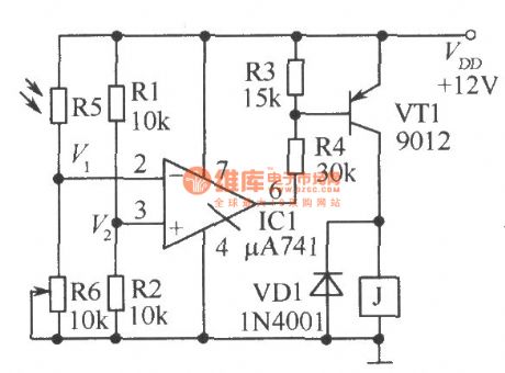
The circuit shown in the picture is a precise optical control circuit, and its work is noteffected by supply voltage and ambient temperature. Resistors R1, R2, R6 andphotosensitive resistor R5 form thetwo bridge of Wheatstone bridge together. (View)
View full Circuit Diagram | Comments | Reading(1713)
simple light-controlled switch
Published:2011/8/28 4:24:00 Author:chopper | Keyword: simple, light-controlled switch
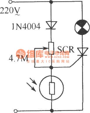
As shown,it is a simple light-controlled switch. In some public places such as corridor, street lightthere are automatical light-controlled switches, which is not only convenient but also saving energy. It will automatically turn on in the dark,and turn offautomatically when it is light.Adjustable 4.7MΩ potentiometeris applicable to different types of photosensitive resistors and can light under certain conditions (dark level). (View)
View full Circuit Diagram | Comments | Reading(2140)
Homemade photoelectric coupler
Published:2011/9/2 23:24:00 Author:chopper | Keyword: Homemade, photoelectric coupler
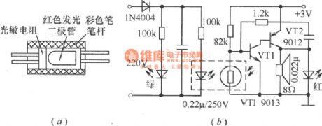
Combine the Φ55mm red LED andphotosensitive resistorby transparent tape and put them into a color pen-holder (black is good),then seal the two ends with glue, and it becomes an photoelectric coupler, which is applied for low-frequency switching circuit,just as shown in Figure (a) . Figure (b) is a outage alarm circuit made by photoelectric coupler, which can send an alarm when the power fails.When the power is available,the red LED of the photoelectric coupler is bright and the resistance of thephotosensitive resistor will decrease after coupling,then VT1 stops,and the oscillator formed by VT1,VT2 does not run. (View)
View full Circuit Diagram | Comments | Reading(1539)
bridge type photoelectric detector formed by photosensitive resistor
Published:2011/9/2 23:22:00 Author:chopper | Keyword: bridge type, photoelectric detector, photosensitive resistor
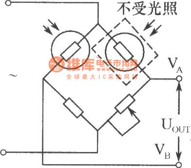
In the industrial photoelectric measuring device, the photosensitive resistor can form the bridge type photoelectric detector, which is shown in the picture. Two same model (darkness resistance equivalent)photosensitive resistors are used as the bridge arms, one for photoelectric detection, and the other sealed with black tape to avoid light for temperature compensation.This bridge type photoelectric detector can adopt the DC or AC. When using AC modulation, it outputs AC signals to reduced null drift of the amplifier. (View)
View full Circuit Diagram | Comments | Reading(1534)
Light automatic regulator circuit
Published:2011/8/28 4:19:00 Author:chopper | Keyword: Light, automatic regulator
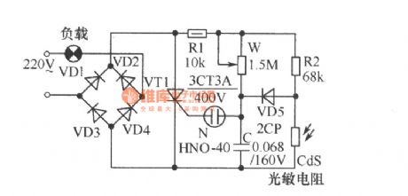
As shown, the circuit can adjust light level according to the strength of outside light automatically. If the external brightness is high, light will be dark, whereas the brightness is low, light will be bright. The thyristor VT1 and diodes VD1~VD4 in figure form full-wave phased circuit with the neontube N as trigger tube of VT1.AdjustingW canchange the charging time constant of capacitor C, that is to change the conduction angle of VT1, in order to control the brightness of the light. (View)
View full Circuit Diagram | Comments | Reading(1650)
Beam blocking alarm
Published:2011/8/25 20:50:00 Author:chopper | Keyword: Beam, blocking alarm
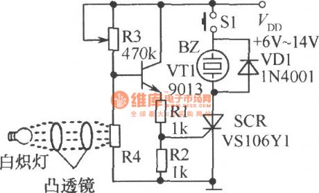
As shown,when the photosensitive resistor R4 is under light, its resistance is small, so the transistor VT1 and unidirectional thyristor SCR are closed; when the beam is blocked, base voltage of VT1rises, and VT1, SCR is conductive, and buzzer BZ will have the power and send an alarm. S1 is the reset switch. When S1 is pressed, the circuit stops the alarm.
(View)
View full Circuit Diagram | Comments | Reading(1437)
precise optical and black control circuit
Published:2011/8/25 20:46:00 Author:chopper | Keyword: precise, optical and black, control circuit
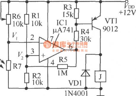
The precise optical and black control circuit is shown as picture. Sinceittakes some positive feedback through R5, changes will be slight behind the actionif the light changes, in order to avoid the frequent jitterof relay when light intensityis on the critical state. (View)
View full Circuit Diagram | Comments | Reading(1503)
photorelay
Published:2011/8/25 20:39:00 Author:chopper | Keyword: photorelay
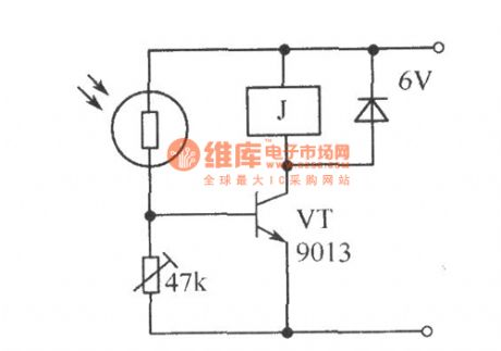
If you use the photosensitive resistoras the optical switch circuit,its sensitivity is very high.The picture shows the photorelay.When the light is low, VT does not turn on; when there is a certain intensity of light exposure, the resistance ofphotosensitive resistor will get small, and VT will get sufficient base current and get conducted, resulting in a larger collector current, and the relay will close. (View)
View full Circuit Diagram | Comments | Reading(1330)
the principle of gas stove flameout alarm
Published:2011/8/19 7:02:00 Author: | Keyword: principle, gas stove, flameout alarm

It is very dangerous if the gas stove is out and nobody finds it.Although thetop gas stoveis with automatic flameout control and protection device, the price is too high to spread. The gas stove flameout alarm shown in the picture can monitor the stove and send out the alarm.Core component is LM324 quad op-amp.IC1-1 is a comparator, IC1-2 is a follower; R4, R5 are the photosensitive resistors, the resistance changes with light intensity; AN is a reset switch for discharging the electric charge of capacitors C1, C2. (View)
View full Circuit Diagram | Comments | Reading(1462)
Electronic candles circuit
Published:2011/8/16 2:11:00 Author: | Keyword: Electronic candles
View full Circuit Diagram | Comments | Reading(1492)
photoelectric controlled electrical socket circuit
Published:2011/8/14 1:26:00 Author:chopper | Keyword: photoelectric controlled, electrical socket
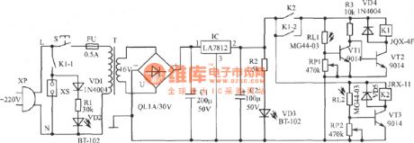
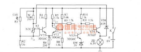
This device adopts ordinary flashlight as remote command,and makes a controlled electrical socket.It can control the power state of electrical socket by pressing the flashlight switch within a few meters,so it is easy to use.IC can be replaced by AN7812,LM7812,W7812 and other models.The current amplification factor β of VT1~VT3 is about 200. RL1 and RL2 use MG44-03 plastic resin encapsulated photosensitive resistors,as well as other ordinary photosensitive resistors whose light photosensitive resistance≤ 5kΩ, dark photosensitive resistance ≥ 1MΩ resistor instead of the . T is the 8W~10W power transformer. (View)
View full Circuit Diagram | Comments | Reading(1474)
application circuit when the TC-3330 monolithic integrated photoelectric switch drives different loads
Published:2011/8/14 1:15:00 Author:chopper | Keyword: application circuit, monolithic, integrated, photoelectric switch, different loads
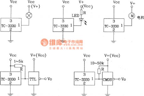
When the TC-3330 monolithic integrated photoelectric switch drives different loads,its application circuit TC-3330 can also be usedon bar code identification,tension sensing, optical cable isolator, paper or object detection, counting, speed measurement and other fields.The photocoupler made by it (diode output type, transistor output type, Darlington type) has excellent performance, high reliability,and wide range of applications. (View)
View full Circuit Diagram | Comments | Reading(1540)
Temperature-voltage transform circuit composed of precision temperature sensor
Published:2011/8/26 3:08:00 Author:Jessie | Keyword: Temperature-voltage transform, temperature sensor
View full Circuit Diagram | Comments | Reading(1516)
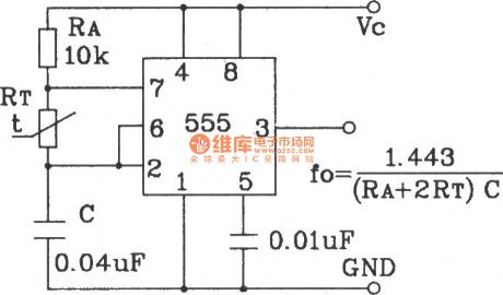
Temperature frequency conversion circuit composed of 555 and precision temperature sensor
Published:2011/8/26 2:50:00 Author:Jessie | Keyword: Temperature frequency conversion, precision temperature sensor
View full Circuit Diagram | Comments | Reading(1605)
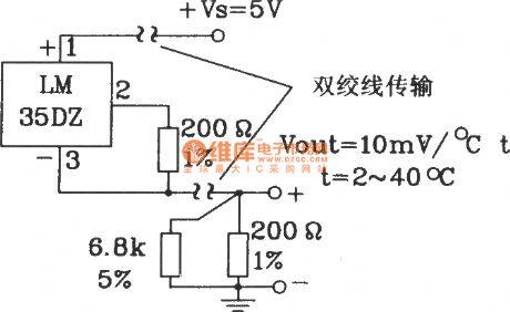
Total positive supply long-distance transmission circuit composed of LM35DZ celsius temperature sensor
Published:2011/8/26 2:49:00 Author:Jessie | Keyword: supply long-distance transmission, celsius temperature sensor
View full Circuit Diagram | Comments | Reading(1283)
| Pages:6/27 1234567891011121314151617181920Under 20 |
Circuit Categories
power supply circuit
Amplifier Circuit
Basic Circuit
LED and Light Circuit
Sensor Circuit
Signal Processing
Electrical Equipment Circuit
Control Circuit
Remote Control Circuit
A/D-D/A Converter Circuit
Audio Circuit
Measuring and Test Circuit
Communication Circuit
Computer-Related Circuit
555 Circuit
Automotive Circuit
Repairing Circuit