
Sensor Circuit
Index 5
Water Switch Sensor Circuit
Published:2012/9/24 22:25:00 Author:muriel | Keyword: Water,Switch,Sensor
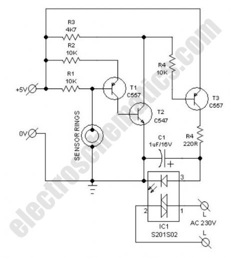
Possible applications for this water switch circuit: rain alarm, watertap leak detector, water level sensor for bathroom water heaters, wetness checker for flower pots and more. This circuit is nothing but a water activated solid-state switch (S201S02) capable of driving ac mains operated loads.How does the water switch circuit worksWorking principle of this circuit is very simple. When the sensor rings are bridged by water, an isolated electric switch turns on to activate the load (an alarm, for instance) connected through its switching contacts. Here, the renowned S201S02 solid-state relay (IC1) is wired as the electronic switch. Any low current 5VDC power unit can be used to feed input supply to the whole circuit.As clearly indicated in the circuit diagram, two closely spaced metal rings are used as the water sensor mechanism. However, one can use two metal needles/injection needles to make the sensor.
Water Switch Circuit Schematic
(View)
View full Circuit Diagram | Comments | Reading(2819)
Simple soil moisture sensor – Arduino Project
Published:2012/9/24 4:15:00 Author:muriel | Keyword: soil, moisture, sensor
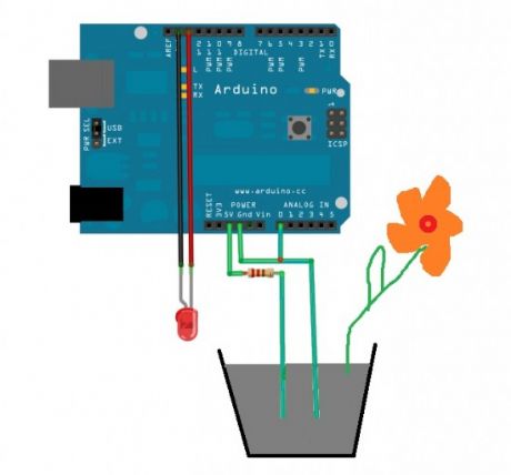
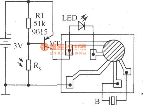
This is a simple arduino project for a soil moisture sensor that will light up a LED at a certain moisture level. It uses Arduino Duemilanove microcontroller board. Two wires placed in the soil pot form a variable resistor, whose resistance varies depending on soil moisture. This variable resistor is connected in a voltage divider configuration, and Arduino collects a voltage proportional to resistance between the 2 wires.Insert the 2 probes (wires, pcb) in the dry soil and measure the resistance value and then pour water and measure it again.Use a mid value for the resistor (eg: 50kΩ for 100kΩ in dry soil and 10kΩ in wet).
The other method to find the resistor’s value is to try different values or use a potentiometer. Insert the probes into the soil that has the desired moisture when to light up the LED and signal that the plant needs water.
Adjust the potentiometer and see the point at which it starts to light. Measure the potentiomenter current value and replace it with a fixed resistor.
Arduino soil moisture sensor schematic
Project source codeconst int VAL_PROBE = 0; // Analog pin 0
const int MOISTURE_LEVEL = 250; // the value after the LED goes ON
void setup() {
Serial.begin(9600);
}
void LedState(int state) {
digitalWrite(13, state);
}
void loop() {
int moisture = analogRead(VAL_PROBE);
Serial.println(moisture);
if(moisture > MOISTURE_LEVEL) {
LedState(HIGH);
} else {
LedState(LOW);
}
delay(100);
}
Source (romanian): http://www.tehnorama.ro/cum-sa-faci-o-floare-sa-te-traga-de-maneca-atunci-cand-ai-uitat-sa-o-uzi/?
2 Responses to “Simple soil moisture sensor – Arduino Project”
(View)
View full Circuit Diagram | Comments | Reading(2887)
Clear Glass Sensor
Published:2012/9/19 21:50:00 Author:Ecco | Keyword: Clear , Glass Sensor

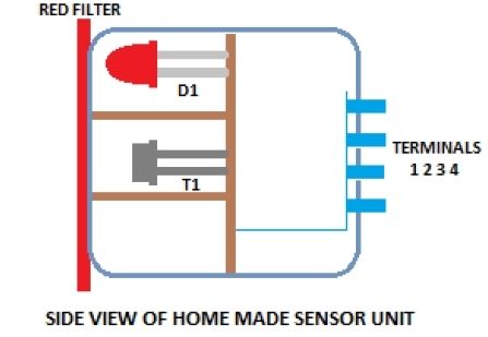
Industrial grade clear glass sensor modules are widely available but not within the reach of an average electronics hobbyist. The simple clear glass sensor circuit can be used for experiment/hobby purposes. The concept is very simple and is based on a home-made sensor unit comprising one high efficiency ultra bright red LED (D1) and a standard phototransistor 2N5777 (T1). The circuits works off a well regulated 5Volt dc supply.When power is turned to ON, light transmitter D1 starts emitting visible red color beam towards outside through a red colored filter glass. If a clear glass is placed in front of it,within 1-5 mm, light from D1 is not highly reflected. So T1 does not conduct and the monoshot wired around IC1 (NE555) is in standby state. This condition is indicated by the green LED (D2).However, in case of some (not all) unclear/colored/labelled glass material, reflected red light from it turn on the phototransistor T1 and IC1 is triggered by this action. Immediately D2 goes off and the piezobuzzer starts beeping for a short duration (near 5 secs with R5, C3 values shown). This acoustic sounder can be replaced with a 5V/600 Ohm relay to control external loads. Remember to add a freewheeling diode (like 1N4148) across the relay coil in antiparallel to suppress the counter emf generated during relay switching.
As stated, the home made sensor consists of an LED, phototransistor and a small piece of red filter glass. If properly aligned (see fig.2) a detection range of 5mm maximum can be expected. Alternatively, you can try a special reflective type opto-sensor (like CNY70) for this purpose. Finally, note that this is a basic design idea and thus, for optimum perfomance retouch the values of components R1, R2, R3, R4 and C2 using theoritical and empirical method.
(View)
View full Circuit Diagram | Comments | Reading(2712)
Light Sensor Circuit
Published:2012/9/19 21:24:00 Author:Ecco | Keyword: Light Sensor
This Circuit can compare the Light level in an area. It uses a PN Photodiode as the light sensor and IC CA3140 as voltage comparator. The circuit is ideal as the front end of burglar alarm circuits.The circuit uses an Op Amp as voltage comparator. In voltage comparator mode, the OpAmp compares the voltage levels between its inverting input (pin2) and the non- inverting input(pin3) and gives an appropriate high / low output. Generally in voltage comparator mode, voltage at one input is kept fixed using a Zener diode or a potential divider resistor chain. In the circuit, the voltage at pin 3 is set by VR1 so as to keep the output high in a particular light level. The high output keeps the LED off. The PN Photodiode act as the light sensor. When the light reduces, current through the photodiode decreases. This increases the voltage at pin 2 of comparator and the output swings to low state. Current then flows through R2 and LED into the comparator and LED lights. This indicates, low light level or darkness.
Light Sensor Circuit
?
4 Responses to “Light Sensor Circuit”
Source: electroschematic.com (View)
View full Circuit Diagram | Comments | Reading(2056)
SEN-1327 LPG Gas Sensor Module
Published:2012/9/18 21:38:00 Author:Ecco | Keyword: LPG, Gas Sensor, Module
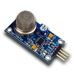
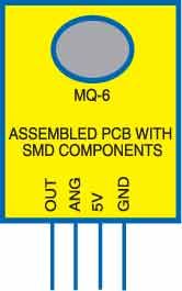
The SEN-1327 LPG Gas Sensor Module is designed to enable LPG detection interface to Microcontroller without ADC Channels. It allows to determine when a preset LPG gas level has been reached or exceeded. Interfacing with the sensor module is done through a 4-pin SIP header and requires One I/O pin from the host microcontroller.The onboard microcontroller provide initial heating interval after powerup and then starts to meassure LPG sensor output.If it found the LPG contents above setted value, it will inform the Host controller by pulling the Output Pin to High and Starts to blink a onboard status LED. The sensor module is mainly intended to provide a means of comparing LPG sources and being able to set an alarm limit when the source becomes excessive.
SEN1327 pins configuration and photo
SEN-1327 module features
Uses the MQ-6 LPG Gas Sensor
Easy SIP interface
Compatible with most microcontrollers
Onboard Status and Power LED
Onboard Pot for threshold setting
On board microcontroller
6 Responses to “SEN-1327 LPG Gas Sensor Module”
(View)
View full Circuit Diagram | Comments | Reading(3853)
Heat Sensor Circuit using LM741
Published:2012/9/16 21:23:00 Author:Ecco | Keyword: Heat Sensor
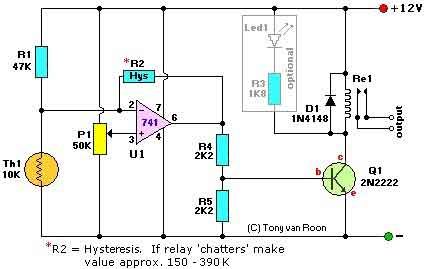
The following page outlines detail information on how to step by step design a Simple Heat Sensor Circuit. This circuit design utilized LM741 as the operational amplifier. (View)
View full Circuit Diagram | Comments | Reading(5983)
Humidity Sensor with the H14DL
Published:2012/9/12 21:04:00 Author:Ecco | Keyword: Humidity Sensor
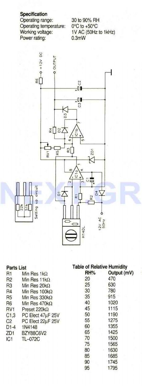
A humidity sensor with temperature compensation built-in. Never apply a DC voltage to the sensor, even measuring the sensor with an ohmmeter will damage the device, always ensure that an AC voltage is applied. Avoid condensation, freezing, dust, mist, oil, alcohol, etc. To set up this circuit replace the H14DL with Min Res 22Kohm and Min Res 51Kohm as shown, Acjust RV1 until a voltmeter between output and ground reads 1.40V.
Source: NEXT.GR (View)
View full Circuit Diagram | Comments | Reading(1431)
Temperature sensor transmitter circuit
Published:2012/9/11 1:30:00 Author:Ecco | Keyword: Temperature sensor, transmitter
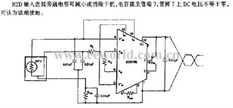
RTD input is connected to bypass capacitor to reduce or eliminate the interference. When the capacitor is connected to pin 7 of pipe, the DC voltage on pin 7 is not equal to zero, that means the pin 7 is grounded.
(View)
View full Circuit Diagram | Comments | Reading(1377)
Temperature sensor interface circuit
Published:2012/9/11 1:23:00 Author:Ecco | Keyword: Temperature sensor, interface
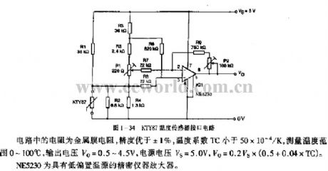
The resistor in circuit uses a metal film resistor, and its precision is better than ± 1 %, temperature coefficient TC is less than 50 × 10-4 / K, measurement temperature range is between 0~ 100 ℃, output voltage Vo = 0.5 ~ 4.5V, supply voltage VS = 5.0 V, Vo = 0.2VS × (0.5 +0.04 × TC). NE5230 is a low bias temperature precision instrument amplifier.
(View)
View full Circuit Diagram | Comments | Reading(1847)
TEMPERATURE SENSOR WITH 4 TO 20mA CURRENT LOOP
Published:2012/9/10 20:24:00 Author:Ecco | Keyword: TEMPERATURE SENSOR , 4 TO 20mA , CURRENT LOOP
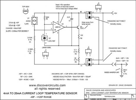
I designed a circuit similar to this one years ago to accurately measure the air temperature inside a building 1000s of feet from a control room. The circuit uses a very robust current loop method. It uses a highly accurate semiconductor temperature sensor and an equally accurate voltage reference. The circuit includes a diode bridge, so it is polarity independent. By using the component values indicated, the circuit should not require calibration. It has a range from ?40F to +120F and an accuracy of +/- one degree F.
Source: discovercircuits (View)
View full Circuit Diagram | Comments | Reading(2389)
LM134-LM10 Thermometer/Temperature Sensor
Published:2012/9/3 3:08:00 Author:Ecco | Keyword: Thermometer, Temperature Sensor
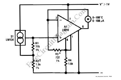
Using LM134 and LM10 integrated circuits, we can build a thermometer which has -55 to 150°C sensing range. The ideal meter for this circuit is a 0-200uA digital ampere meter, which can show both positive and negative polarity. This will make the circuit suitable for indicating temperatures below 0°C. LM134 is basically a current source with very accurate and consistent temperature coefficient, so many temperature sensing application find it suitable for the sensor. Here is the schematic diagram of the circuit: (Source: freecircuitdiagram)
(View)
View full Circuit Diagram | Comments | Reading(2455)
One Direction Motion Sensor
Published:2012/9/3 2:31:00 Author:Ecco | Keyword: One Direction, Motion, Sensor

This is a one direction motion sensor circuit. This motion sensor circuit is used to detects an object passing in one direction, ignoring an object that going to opposite way. This circuit uses two sensors to identify the movement only in one direction. The basic principle of this circuit is simple, where one sensor is used to generate a short pulse, and the other sensor is used to block of turn of the gate. The phototransitors give high output on their collectors when there is an object blocking the light. By a 0.4uF differentiator capacitor, the interruption of light at Q2 sensor will produce short pulse at point C. But this short pulse will only appear at the output if a high signal appears at A. This condition will be satisfied if the light to Q1 is blocked by the object when the object is passing through Q2, means that the direction should be from Q1 to Q2. Here is the schematic diagram of the circuit:(Source: freecircuitdiagram)
(View)
View full Circuit Diagram | Comments | Reading(1945)
T, R-40 Series of universal ultrasonic transmitting, receiving sensor circuit diagram
Published:2011/9/16 1:02:00 Author:Rebekka | Keyword: ultrasonic transmitting, receiving sensor
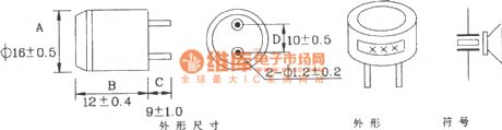
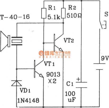
T/R-40 series of ultrasonic sensors works by piezoelectric effect. Usually we also call it transducer. This type of transducer is suitable for anti-theft alarm and remote.
The shape, size and circuit symbols of T/R-40-XX series of ultrasonic sensors.
The ultrasonic transmitter circuit composed of discrete structure.
T/R-40-16 will emit a string of 40kHz ultrasonic signals. The circuit voltage is 9V, operating current is 25mA, control distance can up to 8m.
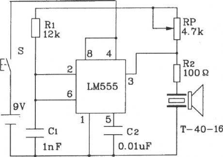
Ultrasonic transmitter circuit composed of 555.
The 40kHz oscillation pulse drives T-40-16 output from 555 of the pin 3, that makes it emit 40kHz ultrasonic signal. Circuit voltageis 9V, operating currentis 40 ~ 45mA, the control distance is more than 8m.
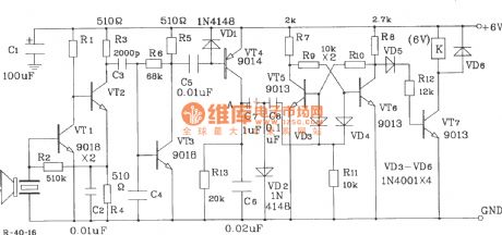
Bistable ultrasonic receiver circuit
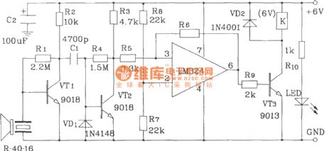
Universal ultrasonic receiver circuit. (View)
View full Circuit Diagram | Comments | Reading(5589)
The micropower battery driver temperature sensor
Published:2011/11/1 21:32:00 Author:Ecco | Keyword: micropower battery , driver , temperature sensor
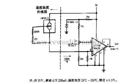
Note: When it works at 25℃, it can adjust the output to 250mV, and the temperature range is 25 to 150℃, the accuracy is ±0.5℃.
(View)
View full Circuit Diagram | Comments | Reading(1409)
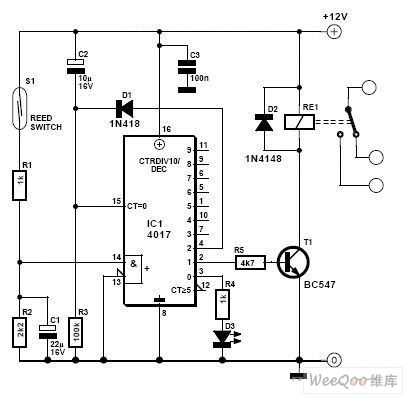
Magnetic reed, dryreed proximity switch sensor circuit diagram using CD4017
Published:2011/10/21 1:41:00 Author:Rebekka | Keyword: Magnetic reed, dryreed , proximity switch sensor
View full Circuit Diagram | Comments | Reading(6615)
camera electronic metering system
Published:2011/9/6 23:34:00 Author:chopper | Keyword: camera, electronic metering system
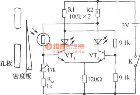
In the midrange camera, CdSphotosensitive resistor is taken as electronic metering device. Light is on the CdSphotosensitive resistorthrough the orifice, and you can move thedensity plate, so that the circuit will achieve a balance, and then two LEDs will light evenly to express the proper exposure.If only onelights while the other does not, it is due to underexposure or over exposure, then moving the density board can achieve the correct exposure purpose.The thermistor RM in the circuit(1kΩ) has temperature compensation function, to compensate error for temperature changes caused by photosensitive resistor. (View)
View full Circuit Diagram | Comments | Reading(1615)
timing battery-conserving switch
Published:2011/9/6 23:34:00 Author:chopper | Keyword: timing, battery-conserving switch
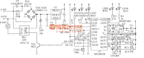
Door lamp isusually controlled by hands,which may make some waste of electrical energy and inconvenience if someone forgets to turn on or turn off.If it can increase light control and timing functions,it can achieve automation and energy-saving effect.The ready-made light-controlled timing ICMG2001B is a cheap 1h-36h,nine-gear optional timing,delay IC,and its peripheral circuit is simple ,and it is with driver of indicator light as well as interface of photoresistor.It adopts cheap 32.768kHz crystal as clock source whose order of accuracy will reach one over one hundred thousand.So it is suitable for automatical control circuit of street lamp. (View)
View full Circuit Diagram | Comments | Reading(1471)
delay energy-saving lamp circuit
Published:2011/9/6 23:33:00 Author:chopper | Keyword: delay, energy-saving lamp
The delay energy-saving lamp shown in the picture is a acousto-optic dual control power-saving delay lamp.It can directly replace ordinary lighting switch without changing the existing lighting circuit and can also control the light bulb not to shine during the day or under strong light even there is a big sound, and it will turn on automatically in the evening or under low light when it encounters some sound (such as voice, footstep, etc.)and it can turn off automatically after about 30s (time can be set).It is suitable for stairs, corridors and other places that just need short lighting. (View)
View full Circuit Diagram | Comments | Reading(2099)
electronic greeting card circuit
Published:2011/9/6 23:25:00 Author:chopper | Keyword: electronic, greeting card
View full Circuit Diagram | Comments | Reading(1917)
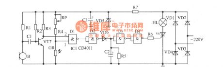
long time delay light-operated switch
Published:2011/9/6 23:28:00 Author:chopper | Keyword: delay, light-operated switch
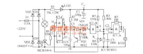
Figure shows the improved sound and light control switch, and its delay time can extend to 3min or so, which can meet the requirements of users well.If you want to continue to extend the dely time when in use,you can clap(make some sound) again when the light bulb is bright,which is more convenient to use.Components selection:IC1 should use dual-input four NAND-gate TC4011. RG is the photoresistance,and its effect is better if the difference between its light resistance and dark resistance is greater.Resistor adopts 1/8W carbon film resistors. (View)
View full Circuit Diagram | Comments | Reading(1955)
| Pages:5/27 1234567891011121314151617181920Under 20 |
Circuit Categories
power supply circuit
Amplifier Circuit
Basic Circuit
LED and Light Circuit
Sensor Circuit
Signal Processing
Electrical Equipment Circuit
Control Circuit
Remote Control Circuit
A/D-D/A Converter Circuit
Audio Circuit
Measuring and Test Circuit
Communication Circuit
Computer-Related Circuit
555 Circuit
Automotive Circuit
Repairing Circuit