
Sensor Circuit
Index 15
ULTRASONIC_PROXIMITY_SENSOR
Published:2009/6/24 21:34:00 Author:May
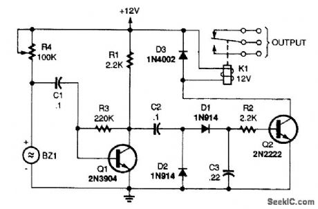
A 100-kΩ potentiometer, R4, sets the cur-rent fed to the Sonalert sounder. The poten-tiometer is adjusted to a point where the sounder just begins to make an audible sound. A single-transistor audio amplifier (Q1) is coupled to the positive side of the sounder and its output is fed to a voltage-doubler circuit. The doubler's dc out-put drives the base of Q2, which, in turn, oper-ates the relay (K1). As long as the Sonalert is producing a sound, the relay stays energized.When a solid object is moved in close prox-imity to the front of the sounder, the Q of the piezo element is lowered and the Sonalert's inter-nal circuit ceases to operate; as a result, the relay drops out. By carefully adjusting R4, the circuit can be made quite sensitive. (View)
View full Circuit Diagram | Comments | Reading(2083)
1IONIZATION_CHAMBER_SMOKE_DETECTOR
Published:2009/6/24 21:20:00 Author:Jessie
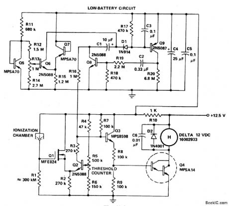
If the smoke alarm signal must be a continuous one rather than pulsating, then the slightly less expensive, all discrete transistor version of the MC14572 may be used. (View)
View full Circuit Diagram | Comments | Reading(2715)
GAS_AND_SMOKE_DETECTOR
Published:2009/6/24 21:13:00 Author:Jessie
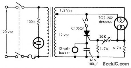
This circuit can detect smoke and a number of gases (CO, CO2, methane, coal gas and others) with a 10 ppm sensitivity. It uses a heated surface semiconductor sensor. Detection occurs when the gas concentration in-crease causes a decrease of the sensor element internal resistance. The switch in series with the SCR is used for resetting the alarm. (View)
View full Circuit Diagram | Comments | Reading(2035)
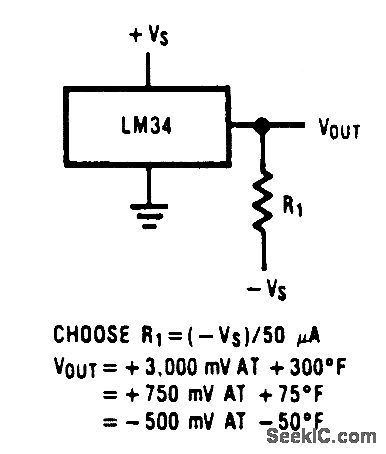
FULL_RANGE_FAHRENHEIT_TEMPERATURE_SENSOR
Published:2009/6/24 4:24:00 Author:May
View full Circuit Diagram | Comments | Reading(998)
FREEZE_UP_SENSOR
Published:2009/6/24 4:31:00 Author:Jessie

Using a bridge circuit to provide an accurate activation temperature, this circuit will turn on a heating unit or other device when the temperature drops below the trip point set by R2. Use a 10-kΩ resistor in place of the thermistor to calibrate it for 32'F activation. (View)
View full Circuit Diagram | Comments | Reading(1170)
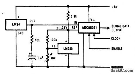
TEMPERATURE_TO_DIGITAL_OUTPUT_CONVERTER
Published:2009/6/24 4:30:00 Author:Jessie
View full Circuit Diagram | Comments | Reading(971)
TEMPERATURE_CONTROLLER_1
Published:2009/6/24 4:29:00 Author:Jessie
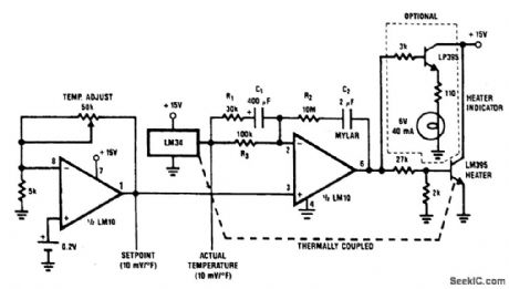
A proportional temperature controller can be made with an LM34 and a few additional parts. The complete circuit is shown. Here, an LM10 serves as both a temperature-setting device and as a driver for the heating unit (an LM395 power transistor). The optional lamp, driven by an LP395 transistor, is for indicating whether or not power is being applied to the heater. (View)
View full Circuit Diagram | Comments | Reading(1963)
THERMOSTATIC_RELAY_APPLICATION
Published:2009/6/24 4:28:00 Author:Jessie
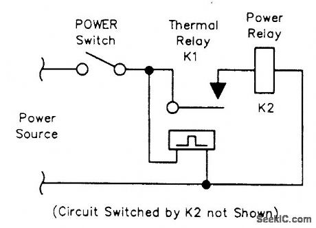
K1, the thermostatic relay, energizes power relay K2, which handles the circuit's power switching. The drawing doesn't show K2's power-switching contacts. (View)
View full Circuit Diagram | Comments | Reading(1105)
TEMPERATURE_DIFFERENTIAL_DETECTOR
Published:2009/6/24 4:28:00 Author:Jessie
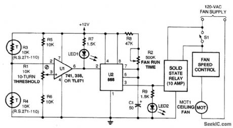
This circuit measures temperature differences, not temperature. Once the difference passes a certain threshold, the timer is triggered, activating the solid-state relay.Op amp U1 is placed in a comparator configuration with two thermistors-one located at the ceiling, one at the floor. The IC senses the temperature difference between the ceiling and floor, but is unaffected by the overall room temperature differential increases. The upper thermistor will de-crease in resistance, eventually causing the voltage at pin 2 of U1 to exceed that pin 2 of U1 to go low and trip the timer. This adds hysteresis to the op amp's output, preventing the motor from chatter-ing. When tripped, the timer activates the relay, which activates the fan. (View)
View full Circuit Diagram | Comments | Reading(3488)
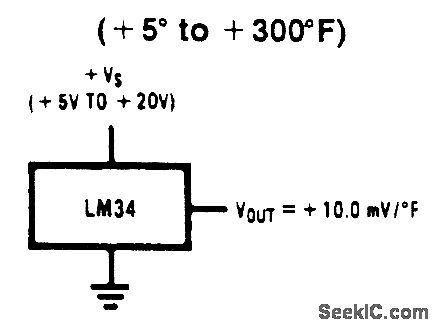
BASIC_FAHRENHEIT_TEMPERATURE_SENSOR
Published:2009/6/24 4:14:00 Author:May
View full Circuit Diagram | Comments | Reading(0)
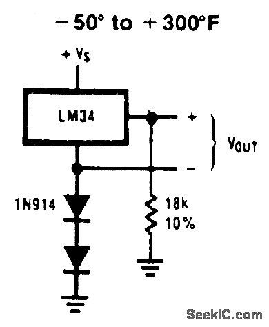
SINGLE_SUPPLY_TEMPERATURE_SENSOR(_50_TO__300°F)
Published:2009/6/24 4:14:00 Author:May
View full Circuit Diagram | Comments | Reading(0)
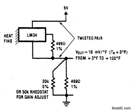
TWO_WIRE_TEMPERATURE_SENSOR_OUTPUT_REFERENCED_TO_GROUND
Published:2009/6/24 4:12:00 Author:May
View full Circuit Diagram | Comments | Reading(1058)
BAR_GRAPH_ROOM_TEMPERATURE_DISPLAY
Published:2009/6/24 4:20:00 Author:Jessie
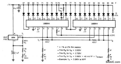
This display shows temperature as a bar graph. The range is 67°F to 86°F. (View)
View full Circuit Diagram | Comments | Reading(0)
OPTOELECTRONIC_PYROMETER
Published:2009/6/24 4:19:00 Author:Jessie
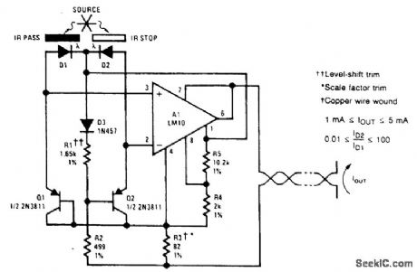
This setup optically measures the temperature of an incandescent body. It makes use of the shift in the emission spectrum of a black body toward shorter wavelengths, as temperature is increased.Optical ffiters are used to split the emission spectrum, with one photodiode being illuminated by short wavelengths (visible light) and the other by long (infrared). The photocurrents are converted to logarithms by Q1 and Q2. These are subtracted to generate an output that varies as the log of the ratio of the illumination irttensiftes. Thus, the circuit is sensitive to changes in spectral distribution, but not intensity. (View)
View full Circuit Diagram | Comments | Reading(2164)
DIFFERENTIAL_THERMOMETER
Published:2009/6/24 4:18:00 Author:Jessie
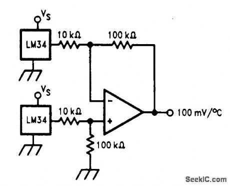
The differential thermometer shown in the figure produces an output voltage which is proportional to the temperature difference between two sensors. This is accomplished by using a dif-ference amplifier to subtract the sensor outputs from one another and then multiplying the differ-ence by a factor of 10 to provide a single-ended output of 100 mV per degree of differential tem-perature. (View)
View full Circuit Diagram | Comments | Reading(1)
TEMPERATURE_TO_FREQUENCY_CONVERTER_CELSIUS
Published:2009/6/24 4:17:00 Author:Jessie
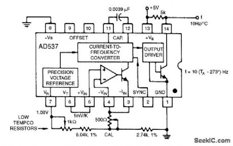
The 1.00-V reference output can be combined with the 1-mV/°K output to realize various temperature scales. For the Celsius scale, the lower end of the timing resistor must be offset by 273 mV. This is easily accomplished, and it results in an output from 0 to 1 kHz for temperatures from 0℃ to +100℃. Other offsets and scale factors are equally easy to implement. (View)
View full Circuit Diagram | Comments | Reading(1827)
BASIC_FAHRENHEIT_TEMPERATURE_SENSOR
Published:2009/6/24 4:14:00 Author:Jessie
View full Circuit Diagram | Comments | Reading(2402)
SINGLE_SUPPLY_TEMPERATURE_SENSOR(_50_TO__300°F)
Published:2009/6/24 4:14:00 Author:Jessie
View full Circuit Diagram | Comments | Reading(1688)
ABSOLUTE_TEMPERATURE_LOG_WITH_RS_232
Published:2009/6/24 4:08:00 Author:Jessie
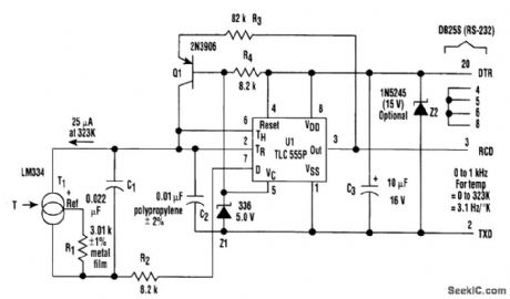
In the setup, T1 (an LM334 temperature sensor) generates a constant current that's propor-tional to absolute temperature, and equal to 25μA at 323 Kelvin (50℃). RI sets this constant of pro-portionality. The current discharges the parallel combination of C1 and C2 connected to the trigger and the threshold pins of UI, which is a CMOS implementation of the venerable 555 analog timer.The negative-going ramp is compared by UI to an internal2.S-V trigger level controlled by 21. When the ramp gets there, U1 triggers. The output pin (3) will go high, presenting a start bit to the con-nected communications port, which causes Q1 to source 100 μA to the timing node. At the same time, the discharge pin (7) will open, allowing R2 and the bottom end of C1 and T1 to be supplied by C1, and isolates it from C2.
Consequently, the current supplied by transistor Q1 will go solely to C2 so that when the result-ing positive-going ramp reaches 5V, exactly 25nC (2.5 V x C2) will have been deposited in the tim-ing node by the recharge cycle because its threshold level (6) will have been reached. This causes both the output pin to return to the negative rail, restoring the marking condition of the R2-232 in-terface, and Q1 to stop recharging C2. U1's discharge pin (7) now connects R2 to the negative rail, causing the charge that was deposited by T1 on C1 during the recharge interval to rapidly redistrib-ute between C1 and C2. This arrangement creates a very linear (0.01%) relationship between T1 cur-rent and pulse output frequency.
While this is happening, the PC's communications port hardware assembles a valid (although meaningless) character because the positive pulse output by UI looks like the start bit of a charac-ter. A simple program running in the PC can then count the frequency of these characters and con-vert the resulting rate into a direct readout of temperature. Because of the 3.1-Hz/degree slope of frequency versus temperature, a 30-second average suffices for 0.01°resolution. (View)
View full Circuit Diagram | Comments | Reading(2327)
NATIONAL_SEMICONDUCTOR
Published:2009/6/24 4:05:00 Author:Jessie
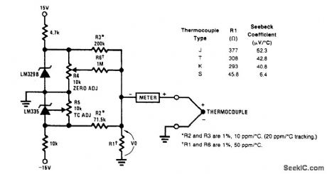
A circuit for use with grounded thermocouples is shown. To trim, short out the LM329B and ad-just R5 so that V°= αT, where cc is the Seebeck coefficient of the thermocouple and T is the absolute temperature. Remove the short and adjust R4 so that W equals the thermocouple output voltage at ambient. A good grounding system is essential here, for any ground differential will appear in series with the thermocouple output. (View)
View full Circuit Diagram | Comments | Reading(1805)
| Pages:15/27 1234567891011121314151617181920Under 20 |
Circuit Categories
power supply circuit
Amplifier Circuit
Basic Circuit
LED and Light Circuit
Sensor Circuit
Signal Processing
Electrical Equipment Circuit
Control Circuit
Remote Control Circuit
A/D-D/A Converter Circuit
Audio Circuit
Measuring and Test Circuit
Communication Circuit
Computer-Related Circuit
555 Circuit
Automotive Circuit
Repairing Circuit