
Sensor Circuit
Index 14
NOISE_BRIDGE
Published:2009/6/26 2:31:00 Author:Jessie


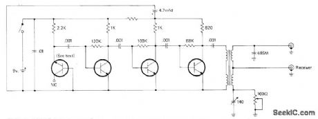
Used with communication receiver to measure impedance at antenna terminals or at end of transmission line, as required for adjusting antenna matching and loading devices for desired impedance at specific frequency. Consists of diode.connected transistor broadband,noise generator, 3-stage noise amplifier, and toroid transformer bridge.
All transistors are 2N5129 or equivalent 2N5137 or 2N5220. Try different transistors until highest noise output is obtained. Toroid core for trans.former is 3/8-inch Indiana General CF102. Quadrifilar winding has 4 1/2 turns of four No.28 enamel wires twisted together, wound on core and connected as on diagram. Noise bridge can also serve as wideband noise source for signal injection during troubleshooting in AF or RF circults, and as noise source for aligning RF cir-cuits,-J.J. Schultz, An Improved Antenna Noise Bridge, CQ, Sept, 1976, p 27-29 and 75. (View)
View full Circuit Diagram | Comments | Reading(3368)
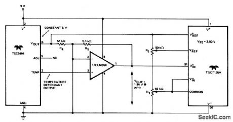
ISOLATED_TEMPERATURE_SENSOR
Published:2009/6/26 1:40:00 Author:May
View full Circuit Diagram | Comments | Reading(2)
μP_CONTROLLED_DIGITAL_THERMOMETER
Published:2009/6/26 1:39:00 Author:May
View full Circuit Diagram | Comments | Reading(994)
CENTIGRADE_CALIBRATED_THERMOCOUPLE_THERMOMETER
Published:2009/6/26 1:38:00 Author:May
View full Circuit Diagram | Comments | Reading(1142)
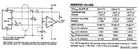
PRECISION_TEMPERATURE_TRANSDUCER_WITH_REMOTE_SENSOR
Published:2009/6/26 1:37:00 Author:May
View full Circuit Diagram | Comments | Reading(1177)
INTEGRATED_CIRCUIT_TEMPERATURE_SENSOR
Published:2009/6/26 1:36:00 Author:May
View full Circuit Diagram | Comments | Reading(1011)
TEMPERATURE_SENSOR
Published:2009/6/26 1:35:00 Author:May
View full Circuit Diagram | Comments | Reading(3236)
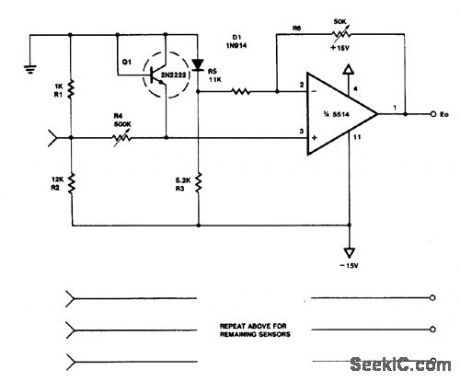
FOUR_CHANNEL_TEMPERATURE_SENSOR(0_50℃)
Published:2009/6/26 1:34:00 Author:May
View full Circuit Diagram | Comments | Reading(834)
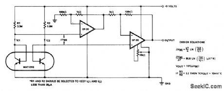
LINEAR_TEMPERATURE_TO_FREQUENC_Y_TRANSCONDUCER
Published:2009/6/26 1:31:00 Author:May
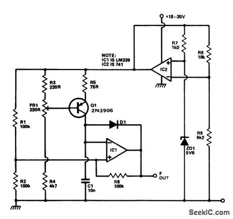
This circuit provides a linear increase of frequency of 10 Hz/℃ over 0-100 ℃ and can thus be used with logic systems, including mi-croprocessors. Temperature probes Q 1 Vb. changes 2.2 mV/℃. This transistor is incorpo-rated in a constant current source circuit. Thus, a current proportional to temperature will be available to charge C1. The circuit is powered via the temperature stable reference voltage supplied by the 741. Comparator IC1 is used as a Schmitt trigger whose output is used to dis-charge C1 via D1 To calibrate the circuit Q1 is immersed in boiling distilled water atad PR1 adjusted to give 1 kHz output. The prototype was found to be accurate to within 0.2 ℃. (View)
View full Circuit Diagram | Comments | Reading(1084)
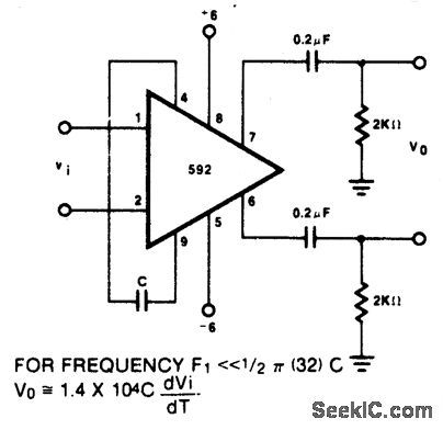
DIFFERENTIATOR_WITH_HIGH_COMMON_MODE_NOISE_REJECTION_
Published:2009/6/25 21:28:00 Author:Jessie
View full Circuit Diagram | Comments | Reading(1162)
SOUND_OPERATED_TWO_WAY_SWITCH
Published:2009/6/25 21:20:00 Author:Jessie
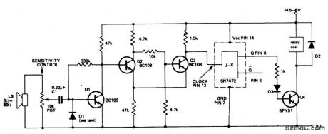
This circuit operates a relay each time a sound of sufficient intensity is made, thus one clap of the hands will switch it one way, a second clap will revert the circuit to the origi-nal condition. Q2 and Q3 form a Schmitt trigger. TheJK flip-flop is used as a bistable whose output changes state every time a pulse is applied to the clock input (pin 12). Q4 allows the output to drive a relay. (View)
View full Circuit Diagram | Comments | Reading(2843)
ACTIVE_INDUCTOR
Published:2009/6/25 21:11:00 Author:May
An active inductor is realized with an eight-lead IC, two carbon resistors, and a small capacitor. A commercial inductor of 50 henries may occupy up to five cubic inches. (View)
View full Circuit Diagram | Comments | Reading(2151)
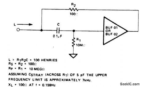
SIMULATED_INDUCTOR
Published:2009/6/25 21:11:00 Author:May
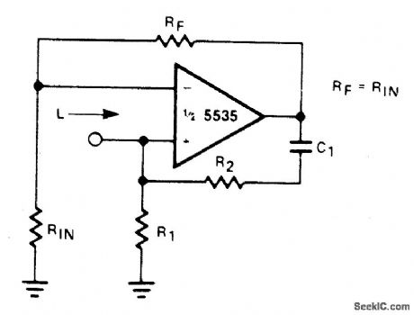
With a constant currentexcitation, the voltage dropped across an inductance increases with frequency. Thus, an active device whose output increases with frequency can be characterizedas an inductance. The circuit yields such a response with the effective inductance being equal to: L = R1R2C. The Q ofthis inductance depends upon RI being equal to R2.At the same time, however, the positive and negative feedback paths of the amplifier are equal leading to the distinct possibility of instability at high frequencies. R1 should, therefore, always be slightly smaller than R2 to assure stable operation. (View)
View full Circuit Diagram | Comments | Reading(0)
TONE_BURST_GENERATOR
Published:2009/6/25 21:09:00 Author:Jessie
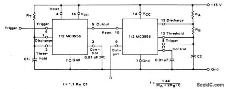
The first timer is used as a monostable and determines the tone duration when triggered by a positive pulse at pin 6. The second timer is enabled by the high output of the monostable. It is connected as an astable and determines the frequency of the tone. (View)
View full Circuit Diagram | Comments | Reading(0)
FOUR_CHANNEL_SYNTHESIZER
Published:2009/6/25 21:05:00 Author:Jessie
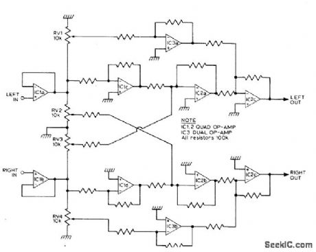
This circuit will synthesize two rear chan-nels for quadraphonic sound when fed with a stereo signal. The rear output for the left chan-nel, is a combination of the left channel input 180 out of phase, added to a proportion of the right hand channel (also out of phase). The right hand rear output is obtained in a similar way. (View)
View full Circuit Diagram | Comments | Reading(1834)
STEREO_REVERB_SYSTEM
Published:2009/6/25 21:04:00 Author:Jessie
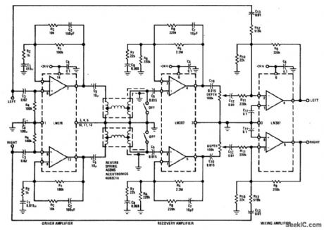
The LM378 dual power amplifier is used as the spring driver. The recovery amplifier is a low noise dual preamplifier. Mixing of the delayed signal with the original is done with another LM387 used in an inverting summing configuration. (View)
View full Circuit Diagram | Comments | Reading(1993)
LEVEL_SENSOR_FOR_CRYOGENIC_FLUIDS
Published:2009/6/25 2:43:00 Author:May
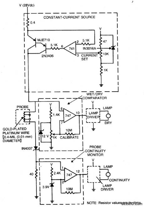
The sensor circuit is adaptable to different liquids and sensors. The constant-current source drives current through the sensing probe and a fixed resistor. The voltage-comparator circuits interpret the voltage drops to tell whether the probe is immersed in liquid and whether there is current in the probe. (View)
View full Circuit Diagram | Comments | Reading(980)
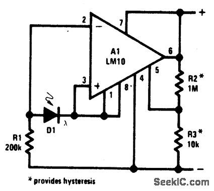
LIGHT_LEVEL_SENSOR
Published:2009/6/24 23:53:00 Author:May
View full Circuit Diagram | Comments | Reading(1176)
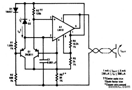
LOGARITHMIC_LIGHT_SENSOR
Published:2009/6/24 23:51:00 Author:May
View full Circuit Diagram | Comments | Reading(1015)
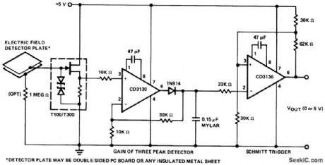
SELF_BIASED_PROXIMITY_SENSOR_WORKS_ON_DETECTED_CHANGING_FIELD
Published:2009/6/24 23:03:00 Author:May
View full Circuit Diagram | Comments | Reading(1642)
| Pages:14/27 1234567891011121314151617181920Under 20 |
Circuit Categories
power supply circuit
Amplifier Circuit
Basic Circuit
LED and Light Circuit
Sensor Circuit
Signal Processing
Electrical Equipment Circuit
Control Circuit
Remote Control Circuit
A/D-D/A Converter Circuit
Audio Circuit
Measuring and Test Circuit
Communication Circuit
Computer-Related Circuit
555 Circuit
Automotive Circuit
Repairing Circuit