
Sensor Circuit
Index 16
MANUAL_CONTROL_FOR_HEATER
Published:2009/6/24 3:53:00 Author:Jessie
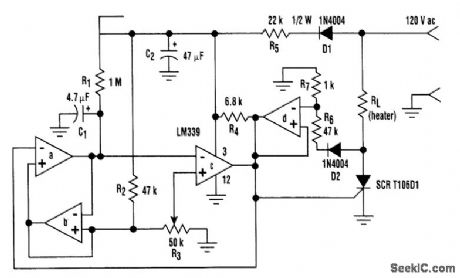
Built around an LM339 quad comparator, this circuit provides manual control of the output of a resistive heater or other load with a long time constant. The circuit's design uses minimal parts, thus it's inexpensive, and generates very low RFI.Comparators a,b, and c form a low-frequency pulse-width modulator. Sections a and b form a sawtooth oscillator (of approximately 0.25 Hz), with capacitor C1 being charged through RI and dis-charged through section a's open collector output. R2 and R3 set the upper voltage limit for the saw-tooth wave. The hysteresis means that C1 is discharged to nearly 0V, creating a voltage swing that is identical to the adjustment range of R3.Comparator c, in conjunction with potentiometer R3, converts the sawtooth wave form to a vari-able duty-cycle drive for the silicon-controlled rectifier.Increasing voltage at R3's wiper means increasing the on time. Section d holds the SCR gate low if the line voltage is above approximately 3.5 V, preventing turn on at mid-cycle and ensuring low RFI.The oscillator frequency is roughly determined by 1/0.7R1C1 Resistance R1 must be greater than 4R2 or the oscillator will lock up. ReducingR1 will increase the lower voltage limit of the sawtooth; in-creasing it might cause lock-up. (View)
View full Circuit Diagram | Comments | Reading(1879)
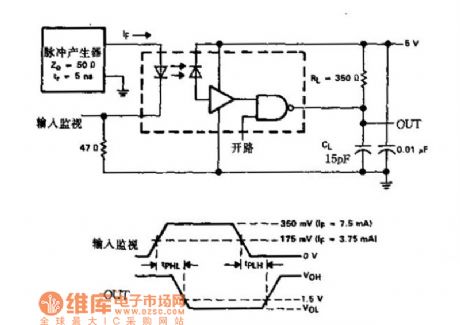
DUAL_INVERTER_LINE_RECEIVER
Published:2009/6/24 3:52:00 Author:Jessie

This circuit is for audio applications. (View)
View full Circuit Diagram | Comments | Reading(1014)
ELECTRONIC_THERMOSTAT
Published:2009/6/24 3:48:00 Author:Jessie
Using a 1N914 diode as a temperature sensor, this straightforward circuit has hysteresis and set-point adjustments. Usable range is about -50 to +150℃. (View)
View full Circuit Diagram | Comments | Reading(2950)
ASTABLE_MULTIVIBRATOR_I
Published:2009/6/23 22:30:00 Author:Jessie
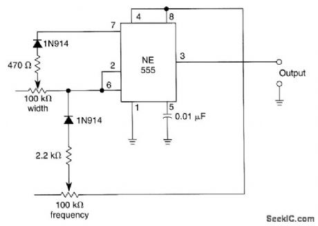
In this multivibrator circuit frequency and pulse width can be separately controlled by using steering diodes (1N914) and two potentiometers. (View)
View full Circuit Diagram | Comments | Reading(1204)
HEARTBEAT_TRANSDUCER
Published:2009/6/23 2:58:00 Author:May
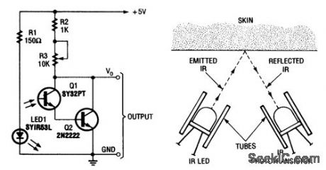
A simple heart-beat transducer can be made from an infrared LED and an infrared phototran-sistor. It works because skin acts as a reflective surface for infrared light. The IR reflectivity of one's skin depends on the density of blood in it. Blood density rises and falls with the pumping action of the heart. So the intensity of infrared reflected by the skin(and thus transmitted to the phototran-sistor)rises and falls with each heartbeat. (View)
View full Circuit Diagram | Comments | Reading(2943)
SIMPLE_INTERCOM_FOR_NOISY_ENVIRONMENTS
Published:2009/6/22 23:51:00 Author:Jessie
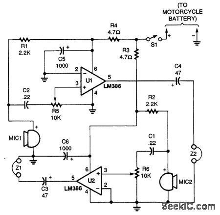
This intercom was originally designed for motorcycle to passenger communications A simple"passenger-to-pilot”ttercom circuit is shown. Two LM386 ICs are connected in a low-gam amplifiercircuit with the headphone output of one paired to the microphone input of the other The microphones are electret elements and the earphones can be of the in-ear type or of the small stereo/monotype that with fit inside a helmet Both amplifiers in the circuit operate at a minimum gain of 20 dB. (View)
View full Circuit Diagram | Comments | Reading(3978)
LOW_TEMPERATURE_SENSOR
Published:2009/6/22 23:13:00 Author:May
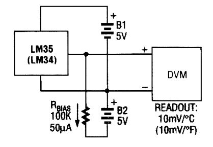
A negative bias current can produce the off-set needed for below-zero readings using the LM34 or LM35 temperature sensor. (View)
View full Circuit Diagram | Comments | Reading(0)
TEMPERATURE_SENSOR
Published:2009/6/22 23:09:00 Author:May
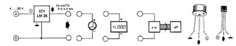
The LM35 temperature sensor provides an output of 10 mV/℃ for every degree Celsius over 0℃. At 20℃ the output voltage is 20 x 10 = 200 mV. The circuit consurnes 60 μA. The load resistance should not be less than 5 kΩ. A 4- to 20-V supply can be used. (View)
View full Circuit Diagram | Comments | Reading(0)
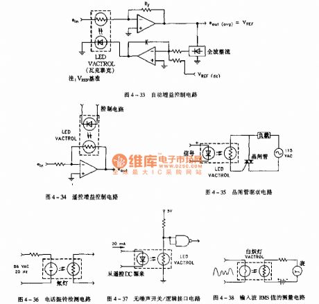
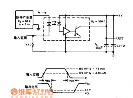
The light sensor application circuit
Published:2011/7/21 2:21:00 Author:Seven | Keyword: light sensor, application circuit
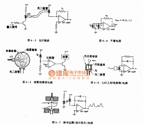
figure 4-7 the pulse minitor(probe) circuit (View)
View full Circuit Diagram | Comments | Reading(952)
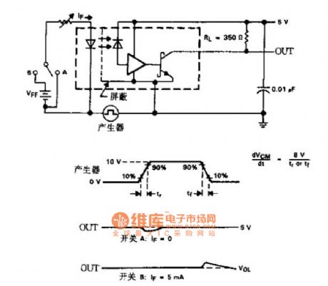
The analog light isolator application circuit
Published:2011/7/21 2:38:00 Author:Seven | Keyword: analog, light isolator, application circuit
View full Circuit Diagram | Comments | Reading(979)
HOOK_SENSOR_ON_4__TO_20_mA_LOOP
Published:2009/6/22 23:05:00 Author:May
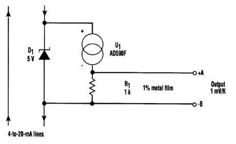
Here's an effective for a temperature sensor to receive power from a 4-to-20 mA loop without actually affecting the loop current (see the figure). This particular temperature sensor IC (AD590F) conducts 1 μA/K when powered by a supply in the range of 4 V to 40 Vdc.The scheme uses a 5-V Zener diode (D1) to regulate the power source for AD590F. Most of the current flows through the Zener diode and a small current flows through AD590F. A high-impedance device can read the temperature information across R1, which is a 1 mV/K in the range of -55℃ to 150℃. The waste of power is negligible in this arrangement. (View)
View full Circuit Diagram | Comments | Reading(1145)
The photocoupler-optoisolator circuit
Published:2011/7/21 2:17:00 Author:Seven | Keyword: photocoupler-optoisolator
View full Circuit Diagram | Comments | Reading(893)
The electric programmable gain amplifier circuit
Published:2011/7/21 2:26:00 Author:Seven | Keyword: programmable gain amplifier
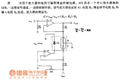
In the figure is the electric programmable gain amplifier circuit which is used in amplifiers. AOI has a LDR whose central head is connected with the ground, one side of it is connected with the signal channel, while the other with the control circuit. The signal amplifier consists of the op-amp A1, resistor R3, gain adjust resistor R2 and input resistor R5, the amplifier gain is shown in the figure.
(View)
View full Circuit Diagram | Comments | Reading(1313)
The dual-channel photocoupler-optoisolator circuit
Published:2011/7/21 2:18:00 Author:Seven | Keyword: dual-channel, photocoupler-optoisolator
View full Circuit Diagram | Comments | Reading(859)
The dual-channel photocoupler-optoisolator anti-interference circuit
Published:2011/7/21 2:19:00 Author:Seven | Keyword: dual-channel, photocoupler-optoisolator, anti-interference
View full Circuit Diagram | Comments | Reading(1091)
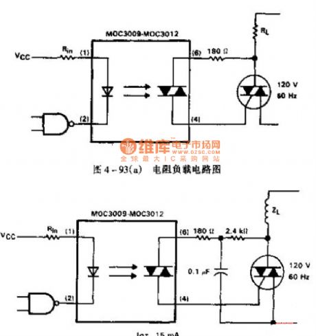
The photocoupler with load circuit
Published:2011/7/21 2:15:00 Author:Seven | Keyword: photocoupler
View full Circuit Diagram | Comments | Reading(1055)
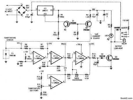
ELECTRONIF_THERMOSTAT
Published:2009/6/22 23:16:00 Author:Jessie
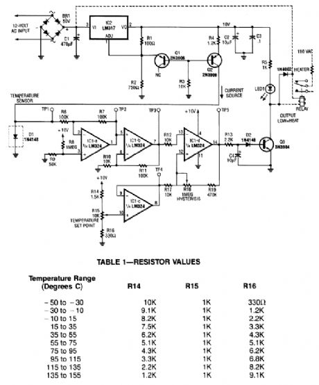
A diode, such as a IN4148, has a typical -2m V/℃ temperature coefficient at a 1 mA diode cur-rent. Q1 and Q2 form a constant current source. D1 is the temperature sensor. IC1-a and -b are dc amplifiers, with IC1-c a temperature reference voltage supply. IC1-d is a comparator with variable hysteresis. R14, R15, and R16 are chosen depending on the thermostat range desired. Q3 is a relay driver (2N3904). The relay used should handle the Ioad current or an optoisolator triac combination can be used. (View)
View full Circuit Diagram | Comments | Reading(3381)
LOW_TEMPERATURE_SENSOR
Published:2009/6/22 23:13:00 Author:Jessie
A negative bias current can produce the off-set needed for below-zero readings using the LM34 or LM35 temperature sensor. (View)
View full Circuit Diagram | Comments | Reading(2804)
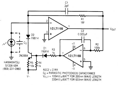
LOU_NOISE_LIGHT_SENSOR_WITH_dc_SERVO
Published:2009/6/22 22:40:00 Author:May
View full Circuit Diagram | Comments | Reading(1520)
TACHOMETER_ADAPTER
Published:2009/6/22 22:36:00 Author:May
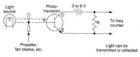

Use of a phototransistor and light source can enable a frequency counter to act as a tachometer:The light source is interrupted by the number of propeller blades, fan blades, spokes, or other marking. R can be anywhere from 1 to 100 kΩ. Try several values for best results. (View)
View full Circuit Diagram | Comments | Reading(1217)
| Pages:16/27 1234567891011121314151617181920Under 20 |
Circuit Categories
power supply circuit
Amplifier Circuit
Basic Circuit
LED and Light Circuit
Sensor Circuit
Signal Processing
Electrical Equipment Circuit
Control Circuit
Remote Control Circuit
A/D-D/A Converter Circuit
Audio Circuit
Measuring and Test Circuit
Communication Circuit
Computer-Related Circuit
555 Circuit
Automotive Circuit
Repairing Circuit