
Sensor Circuit
Index 4
Sensor Circuit
Published:2013/1/29 21:23:00 Author:muriel | Keyword: Sensor Circuit
View full Circuit Diagram | Comments | Reading(3090)
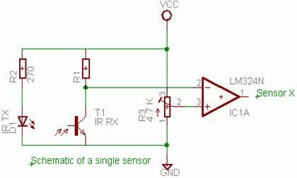
Line Tracking Sensor
Published:2013/1/29 21:15:00 Author:muriel | Keyword: Line Tracking Sensor

View full Circuit Diagram | Comments | Reading(1632)
1.5V LED Flasher Oscillators
Published:2012/12/23 20:59:00 Author:muriel | Keyword: 1.5V, LED Flasher, Oscillator
View full Circuit Diagram | Comments | Reading(1721)
LCD RF Power meter, AD8307 sensor schematic
Published:2012/11/9 20:49:00 Author:muriel | Keyword: LCD, RF, Power meter, AD8307 , sensor schematic

View full Circuit Diagram | Comments | Reading(5627)
IR slotted switch sensor
Published:2012/11/9 0:32:00 Author:muriel | Keyword: IR slotted switch, sensor
There is a type of detector known as a slotted switch that consists of a phototransistor/LED pair mounted on a solid frame with a small air gap between the two elements. A typical circuit might be:
o +5v o +5v
| |
| |
\ \
220 ohms / / 4.7K
\ \
/ /
| |
| +-------> Vout
_|_ /
\ / |/
----- |\ NPN
| \
| |
| |
| |
GND GND
| air gap |
When the air gap is unobstructed, the transistor saturates, pulling Vout to ground; when the gap is blocked, the transistor cuts off and Vout is +5 volts. (View)
View full Circuit Diagram | Comments | Reading(1307)
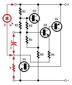
Sensor and Relay Circuits
Published:2012/10/25 21:29:00 Author:muriel | Keyword: Sensor , Relay Circuits

In Figure, I have shown the reed relay connections, together with an efficiency circuit (R13 & C4), that will reduce the holding current to the bare minimum. C4 is used to provide an initial full voltage to the relay coil, to ensure that it will pull in reliably. After C4 is charged, the only current flows through R13, and the current is just sufficient to keep the relay energised, so current drain is minimised. You may need to adjust the value of R13 depending on the relays used - as shown, it is suitable for a 12V reed relay with a coil resistance of around 1k ohm, and limits holding current to approximately 7.5mA. R16 is optional but recommended. It ensures that switching is clean , with no relay chattering. The series combination of R7 and R15 can be replaced with a single 51k resistor if preferred.
The sensor works by detecting the voltage dropped across the sense resistor. When current is drawn, a small voltage is developed across the resistor (R8), and this is used to switch the opamp from a normally high output state to a voltage of about 2V. This switches off Q1, which in turn de-activates the relay and disconnects the charger. When the external circuit is switched off, the voltage across the sense resistor falls to near zero, the opamp changes output state, and the relays are energised, thus reconnecting the charger.
The charger must be able to supply enough current to keep the relays energised, as well as provide power to charge the batteries (and power U1 - typically about 2.5mA), so minimising relay current is important.
If you switch the power to your external equipment on-off-on-off quickly, you may find that the relay does not re-activate after the last power-off. This can happen if C4 is charged, and has not had time to discharge fully, so the relay coil doesn't get the pulse needed to close the contacts. The easy way to prevent this is not to switch on and off rapidly. (View)
View full Circuit Diagram | Comments | Reading(2014)
LED| Photo Sensor.
Published:2012/10/18 2:16:00 Author:muriel | Keyword: LED, Photo Sensor

Here's a circuit that takes advantage of the photo-voltaic voltage of an ordinary LED. The LED voltage is buffered by a junction FET transistor and then applied to the inverting input of an op-amp with a gain of about 20. This produces a change of about 5 volts at the output from darkness to bright light. The 100K potentiometer can be set so that the output is around 7 volts in darkness and falls to about 2 volts in bright light.
(View)
View full Circuit Diagram | Comments | Reading(1761)
Temperature sensor current transmission circuit
Published:2012/10/11 21:21:00 Author:Ecco | Keyword: Temperature sensor, current transmission
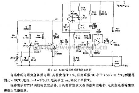
Resistors in the circuit use metal film resistors, and its accuracy is better than 1%, and the temperature coefficient TC is less than ± 50 × 10-6 / k; measuring range: 0 to 100 ° C , the current I = 4 + T/6.25, current unit is mA, and temperature T unit is ℃. The circuit is composed of KTY87 two-wire current transducer, Wheatstone bridge with preamplifier, current transmitter output stage and regulator.
(View)
View full Circuit Diagram | Comments | Reading(2202)
Presence detector, proximity sensor circuit
Published:2012/10/11 21:16:00 Author:muriel | Keyword: Presence detector, proximity sensor

This circuit reacts in presence of any conductor object including humans. This circuit does not detect object movement but can act as an proximity sensor!Sensitivity is adjustable with P1 which will be located at a great distance from the rest of the presence detector circuit.
Presence, proximity sensor circuit diagram
(View)
View full Circuit Diagram | Comments | Reading(2927)
Seismic Sensor circuit
Published:2012/10/10 1:50:00 Author:muriel | Keyword: Seismic Sensor
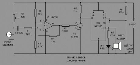
Here is an ultra sensitive vibration alarm that can sense very minute earth borne vibrations. It can be used to detect vibrations in the earth (Earth quake?). So it is an ideal device to monitor entry passages. The circuit exploits the direct piezo electric property of the piezo element used in buzzers.The Lead Zirconate crystals present in the piezoelement can readily store current and can release the current when the orientations of the crystals are disturbed through mechanical vibrations. IC1 amplifies the signals from the piezo element and the high output from IC1 switches on T1. When T1 conducts, trigger pin 2 of the monostable (IC2) will grounded to give 3 minutes high output.
This high output is used to sound alarm and to light LED. VR adjusts the sensitivity of piezo element. Glue the fine side of the piezo element on the floor (if used as an entry alarm) or inside a metal box (if used to bury in soil to detect earth borne vibrations).
Seismic Sensor Circuit Diagram
(View)
View full Circuit Diagram | Comments | Reading(3141)
Heat Sensor Circuit
Published:2012/10/10 1:49:00 Author:muriel | Keyword: Heat Sensor
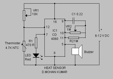
This simple circuit senses heat from electronic devices and gives warning alarm.It is an ideal add on circuit to monitor heat in CD players, Amplifiers etc.
(View)
View full Circuit Diagram | Comments | Reading(3322)
Water Level Sensor Circuit
Published:2012/10/9 2:37:00 Author:muriel | Keyword: Water Level, Sensor
This simple water level sensor circuit monitors the presence of water in a certain location or container. The circuit sends an acoustic alarm when it senses a drop of water leak. It is very simple to build and it is made of a single IC and some passive components. Check out the water level indicator circuit too!The IC LM1801 is a low power comparator that can deliver high output current if needed. When water hits the sensor, the reference voltage is overshot and the IC drives the ceramic transducer to beep. It is also possible to connect several sensors to the water level monitor circuit. The sensor can be easibly made out of a small piece of PCB that is etched with the proper pattern. The decoupling capacitor C3 is a 100uF/16V electrolytic capacitor.
Water Level Sensor Circuit Diagram
Water Level Sensor PCB and Parts
(View)
View full Circuit Diagram | Comments | Reading(2957)
Radiation Sensor Circuit
Published:2012/10/8 2:41:00 Author:muriel | Keyword: Radiation Sensor
Here is a simple tool to check the degree of radiation from an electric or electronic instrument. The LEDs in the circuit will give a running light pattern at the moment the circuit senses electromagnetic radiation from the device. It can detect radiation from the Computer or TV from a distance of 2 feet or more.The speed of running light depends on the intensity of radiation. Fast running light indicates high amount of radiation and vice versa.IC CD4033 is the decade counter with7 segment display driver. It has seven outputs to drive LEDs or Seven segment display. The clock input (pin1) of IC is very sensitive and readily accepts energy from the electromagnetic radiation even from a long distance. This property of the IC CD4033 is exploited here to measure the intensity of radiation.The reset pin 15 of IC is connected to C1 and R1 to reset the IC after completing a cycle.So that the functioning of IC continues till the input pulses cease.
Areal
A small length plastic wire can be used as areal. A telescopic areal used in pocket radio will give an elegant look to the gadget
Test
Bring the areal close to the TV or CRT monitor of computer. All the LEDs light up one by one giving a running pattern. The speed of running light depends on the strength of radiation. Move away the unit from the monitor. As the diastance increases, speed of running light decreases. Finally all the LEDs stop glowing. This is the point without the radiation. Check all the electric instruments and mains wiring using the device and find out how much radiation is emitting.
Radiation Sensor Circuit diagram
CD4033
CRT Monitor
IC CD4033
(View)
View full Circuit Diagram | Comments | Reading(2130)
Isolated programmable voltage / current sensor 1B22 used in pressure measurement system
Published:2012/10/7 21:43:00 Author:Ecco | Keyword: Isolated , programmable voltage, current sensor , pressure measurement system
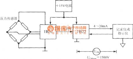
The output signal of pressure sensor 1B32 firstly converted into 0 ~ +10 V voltage signal by bridge sensor signal conditioner, then the 1B22 converts it into 4 ~ 20mA current signal which is finally sent to recorder or indicator. The highest insulation voltage = 1500V ( RMS) UCMmax between public ground of secondary instrument and the power ground of 1B22.
(View)
View full Circuit Diagram | Comments | Reading(1591)
Unipolar mode temperature compensation circuit with linear output integrated magnetic field sensor AD22151
Published:2012/10/7 21:28:00 Author:Ecco | Keyword: Unipolar mode, temperature compensation, linear output , integrated, magnetic field sensor
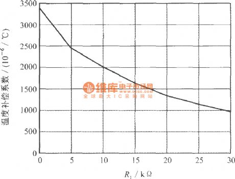
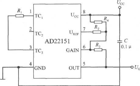
The feature is that R1 is connected between the TC1 end and TC3 end, so that the potential of magnetic null point is not equal to UCC / 2 to compensate for the high temperature coefficient below -2000 × 10-6/ ℃. When TC2 end is open, the compensating resistor R1 and internal resistor RB form the temperature compensation coefficient voltage divider. Under unipolar mode, the relationship curve between R1 resistance value and temperature compensation coefficient is shown as below.
(View)
View full Circuit Diagram | Comments | Reading(2426)
Cold Sensor Circuit
Published:2012/10/7 21:15:00 Author:muriel | Keyword: Cold Sensor
This circuit monitors the temperature level in Air-conditioned rooms, Labs, Cold storage etc. and intimate you whether the low temperature is maintained in the room or not. It gives audio visual indications when the Air-conditioning system or freezing system fails and temperature rises. This prevents the spoilage of stored materials. If the temperature is above the preset level, it gives LED indications first and after Four minutes it gives loud beeps inviting immediate attention.The circuit uses NTC Thermister as temperature sensor. Its resistance decreases when the temperature in its vicinity increases above one degree or more.IC1 is wired as a voltage comparator with its inverting and non inverting inputs tied to two potential dividers. The non inverting input (pin3) receives a variable voltage from the potential divider comprising the NTC Thermister and VR1. Similarly, the inverting input (pin 2) also receives an adjustable voltage from the potential divider R1 and VR2. Preset VR1 adjusts the voltage level at pin 3 slightly lower than that of pin 2 in the idle state in which the room temperature is below 26 degree. VR2 adjusts the voltage level at pin2 of IC1 slightly higher than that of pin 3.
Cold Sensor Circuit diagram
Errata : Pin 8 of IC CD4060 is ground. It should be connected to negative rail.
Normally IC1 will give Zero volt output since its pin3 gets lower voltage than pin2.This is due to high resistance of Thermister in cold. When the Refrigeration system fails, room temperature rises above 30 degree and the resistance of Thermister decreases. This allows more current to flow into pin 3 and output of IC1 becomes high. This triggers T1 and Yellow LED turns on indicating that the room temperature is rising. If this condition persists, T1 remains conducting and the reset pin 12 of IC2 reach the ground potential and the IC2 starts oscillating. With the given values of C1 and R5, Q8 output becomes high after 2 minutes. This makes the Red LED flashing. If the condition continues, Q9 output becomes high after 4 minutes and buzzer starts beeping. In short, if the refrigeration system is not restarted within 4 minutes buzzer beeps to invite the attention.
NTC Thermister and IC CD4060
(View)
View full Circuit Diagram | Comments | Reading(1642)
Uniaxial magnetic field sensor with the serial interface ( integrated magnetic field sensor HMC1001)
Published:2012/9/27 21:12:00 Author:Ecco | Keyword: Uniaxial, magnetic field , sensor , the serial interface , integrated
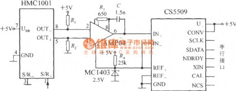
The output stage of the circuit uses a 16-bit A / D converter CS5509 which can be matched with a microprocessor or microcontroller by interface circuit. The AMP04's output voltage (Uo) is connected to CS5509 analog input end, and MC1403 bandgap reference voltage source provides 2.5V reference voltage for CS5509.
(View)
View full Circuit Diagram | Comments | Reading(2015)
Piezoelectric Heat Sensor
Published:2012/9/27 21:28:00 Author:muriel | Keyword: Piezoelectric, Heat, Sensor
Here is an Ultrasensitive Heat Sensor to monitor high temperature in Electronic devices. It can be placed inside the electronic gadget that usually generates heat during its operation. The circuit also functions as a sensitive Fire Alarm. This heat sensor uses the piezoelectric property to sense heat.
The sensor element is the ordinary piezo disc found in buzzer. The middle part of the piezo disc is coated with a layer of piezo electric material called Lead Zirconate. The crystals in this material are capable of dis-orientation and re-orientation when it is subjected to mechanical, electrical and heat stress. The Direct Piezo electric property of the piezoelectric crystals is the ability to generate electric signals when the crystals dis-orient and re-orient following a stress. This property is used here to sense temperature.
Piezoelectric Heat Sensor Circuit
A high gain type OP-Amp is used to sense the electrical signals from the piezo disc. The inverting (pin2) and non – inverting (pin3) inputs of the Op-Amp IC CA3140 are shorted through the capacitor C1, so that both the inputs will be in a balanced state. When this happens, output of IC1 remains low. When the piezo disc is subjected to heat stress, it generates a very small current that is enough for upsetting the balance of the inputs of IC1. This changes the output of IC1 from low to high. This high output is used to activate the alarm circuit based on the ROM IC UM3561.
Piezo Disc (View)
View full Circuit Diagram | Comments | Reading(1594)
Magnetic Field Sensor circuit
Published:2012/9/26 21:37:00 Author:muriel | Keyword: Magnetic, Field Sensor

This DIY magnetic field sensor circuit is very simple and can detect fixed magnetic fields or fields that are varying at an audio frequency. The unit is not intended to provide accurate measurement of magnetic field strength.
A small and not very powerfull bar magnet can be detected at about 100 mm from the sensor. It has a Hall Effect sensor (UGN3503U) and IC2 (OP77GP or TL071CP), a precision opamp which is used to provide some additional amplification. Meter ME1 is connected between the output of IC2 and the potential divider and it therefore responds to the voltage difference between the two. If audio rather than DC performance is of most importance it would be advisable to use TL071CP for IC2 and then reduce the output resistor from 33k to 27k.
A 6V battery supplies power to the magnetic field sensor circuit and the current consumption is only about 9mA. Do no use a 9V battery as this will result in the maximum supply voltage rating of IC1 being exceeded.
DIY Magnetic Field Sensor Circuit Diagram
(View)
View full Circuit Diagram | Comments | Reading(4131)
Line Following Robot Sensor
Published:2012/9/25 21:44:00 Author:muriel | Keyword: Line Following, Robot, Sensor

This Line Following Robot sensor or surface scanner for robots is a very simple, stamp-sized, short range (5-10mm) Infrared proximity detector wired around a standard reflective opto-sensor CNY70(IC1). In some disciplines, a line following robot or an electronic toy vehicle go along a predrawn black line on a white surface. In such devices, a surface scanner, pointed at the surface is used to align the right track.IC1 contains an infrared LED and a phototransistor. The LED emit invisible infrared light on the track and the phototransistor works as a receiver. Usually, black colored surface reflects less light than white surface and more current will flow through the phototransistor when it is above a white surface. When a reflection is detected (IR light falls on the phototransistor) a current flows through R2 to ground which generates a voltage drop at the base of T1 to make it conduct. As a result, transistor T2 start conducting and the visual indicator LED(D1) lights up. Capacitor C2 works as a mini buffer.After construction and installation, the scanner needs to be calibrated. Initially set P1 to its mechanical centre position and place the robot above the white portion of the track. Now slowly turn P1 to get a good response from D1. After this, fine tune P1 to reduce false detection caused by external light sources. Also ensure that the LED remains in off condition when the sensor module is on the blackarea. Repeat the process until the correct calibration is achieved.
The red color LED (D1) is only a visual indicator. You can add a suitable (5V) reed relay in parallel with D1-R4 wiring after suitable alterations to brake/stop/redirect the robot. Similarly, the High to low (H-L) transition at the collector of T2 can be used as a signal to control the logic blocks of the robot. Resistor R1 determines the operating current of the IRLED inside IC1. The sensing ability largely depends on the reflective properties of the markings on the track and the strength of the light output from IC1.
Line Follower Robot Scanner Schematic
(View)
View full Circuit Diagram | Comments | Reading(3186)
| Pages:4/27 1234567891011121314151617181920Under 20 |
Circuit Categories
power supply circuit
Amplifier Circuit
Basic Circuit
LED and Light Circuit
Sensor Circuit
Signal Processing
Electrical Equipment Circuit
Control Circuit
Remote Control Circuit
A/D-D/A Converter Circuit
Audio Circuit
Measuring and Test Circuit
Communication Circuit
Computer-Related Circuit
555 Circuit
Automotive Circuit
Repairing Circuit