
Signal Processing
Index 12
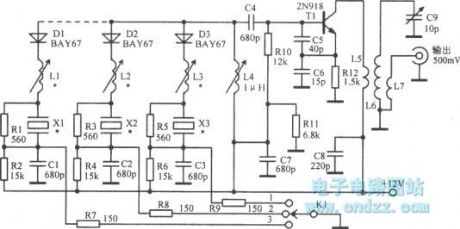
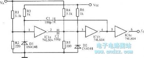
18 ~ 60MHz third harmonic oscillator
Published:2013/3/15 3:07:00 Author:Ecco | Keyword: 18 ~ 60MHz, third harmonic, oscillator
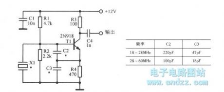
18 ~ 60MHz third harmonic oscillator is shown as figure.
(View)
View full Circuit Diagram | Comments | Reading(1539)
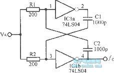
15 ~ 65MHz third harmonic oscillator
Published:2013/3/15 2:59:00 Author:Ecco | Keyword: 15 ~ 65MHz, third harmonic oscillator
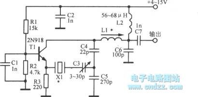
15 ~ 65MHz third harmonic oscillator is shown as figure.
(View)
View full Circuit Diagram | Comments | Reading(1162)
LED on -off time controlled oscillator
Published:2013/3/15 3:06:00 Author:Ecco | Keyword: LED , on -off time, controlled oscillator
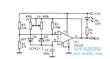
LED on -off time controlled oscillator is shown as figure.
(View)
View full Circuit Diagram | Comments | Reading(861)
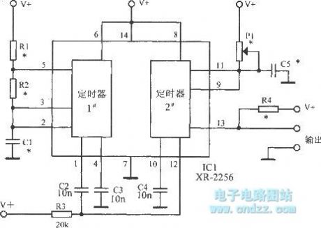
Dual astable multivibrator using 556
Published:2013/3/14 1:46:00 Author:Ecco | Keyword: Dual astable multivibrator
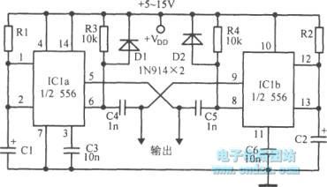
Dual astable multivibrator using 556 is shown as figure.
(View)
View full Circuit Diagram | Comments | Reading(2411)
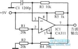
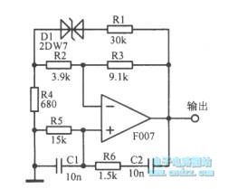
The square wave generating circuit using op amp
Published:2013/3/14 1:41:00 Author:Ecco | Keyword: square wave generating, op amp
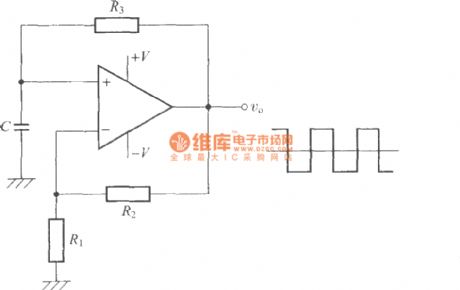
The square wave generating circuit using op amp is shown as figure.
(View)
View full Circuit Diagram | Comments | Reading(1171)
Programmable astable multivibrator
Published:2013/3/14 1:43:00 Author:Ecco | Keyword: Programmable astable multivibrator
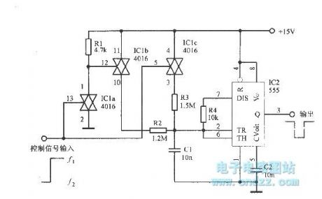
Programmable astable multivibrator is shown as figure.
(View)
View full Circuit Diagram | Comments | Reading(1562)
The switching harmonic crystal oscillator
Published:2013/3/7 2:34:00 Author:Ecco | Keyword: switching, harmonic , crystal oscillator
The switching harmonic crystal oscillator is shown as figure.
(View)
View full Circuit Diagram | Comments | Reading(1286)
Voltage controlled multivibrator circuit
Published:2013/3/14 1:38:00 Author:Ecco | Keyword: Voltage controlled multivibrator
Voltage controlled multivibrator circuit is shown as figure.
(View)
View full Circuit Diagram | Comments | Reading(1219)
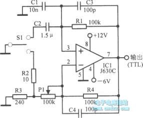
The voltage controlled TTL symmetrical multivibrator
Published:2013/3/14 1:45:00 Author:Ecco | Keyword: voltage controlled, TTL symmetrical multivibrator
The voltage controlled TTL symmetrical multivibrator is shown as figure.
(View)
View full Circuit Diagram | Comments | Reading(1159)
Oscillator circuit using LM3900
Published:2013/3/14 1:51:00 Author:Ecco | Keyword: Oscillator
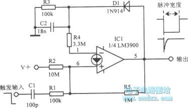
Oscillator circuit using LM3900 is shown as figure.
(View)
View full Circuit Diagram | Comments | Reading(1147)
The bistable multivibrator circuit diagram
Published:2013/3/14 1:52:00 Author:Ecco | Keyword: Bistable multivibrator
Bistable multivibrator circuit diagram is shown as figure.
(View)
View full Circuit Diagram | Comments | Reading(1088)
100kHz self-excited multivibrator
Published:2013/3/7 2:38:00 Author:Ecco | Keyword: 100kHz , self-excited multivibrator
100kHz self-excited multivibrator is shown as figure.
(View)
View full Circuit Diagram | Comments | Reading(912)
Pulse forming circuit with integral circuit
Published:2013/3/12 3:32:00 Author:Ecco | Keyword: Pulse forming , integral circuit
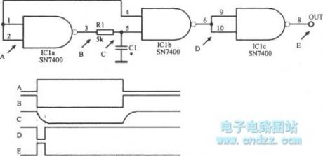
Pulse forming circuit with integral circuit is shown as figure.
(View)
View full Circuit Diagram | Comments | Reading(1106)
1Hz clock signal oscillator
Published:2013/3/12 3:27:00 Author:Ecco | Keyword: 1Hz , clock signal oscillator
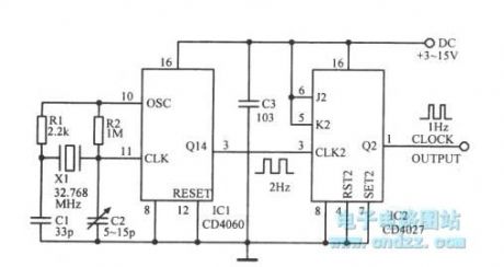
1Hz clock signal oscillator is shown as figure.
(View)
View full Circuit Diagram | Comments | Reading(2954)
0.5 seconds tone burst circuit
Published:2013/3/12 3:29:00 Author:Ecco | Keyword: 0.5 seconds , tone burst circuit
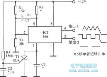
0.5 seconds tone burst circuit is shown as figure.
(View)
View full Circuit Diagram | Comments | Reading(943)
Smooth Tone Clickless CW Sidetone Generator
Published:2013/3/7 3:08:00 Author:Ecco | Keyword: Smooth Tone, Clickless, CW Sidetone Generator
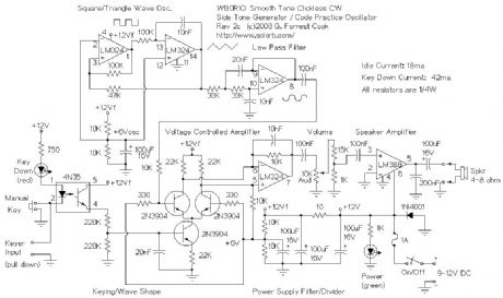
This circuit is essentially a minimal version of an analog music synthesizer that is hard-wired for the purpose of making morse code tones.
The oscillator section produces a fixed frequency triangle wave on LM324 pin 14, that is fed into a low pass filter to get a sine wave on LM324 pin 8. A triangle wave can be thought of as a series of sine waves with decreasing amplitudes as the frequency increases. The low pass filter simply removes the upper harmonics and passes the fundamental sine wave frequency through.
The sine wave is sent to a voltage controlled amplifier made from three 2N3904 transistors. The upper two 2N3904 transistors should be a matched-gain pair in order to minimize thumping sounds. The VCA is modulated with a keying waveform to produce the resulting modulated waveform. The keying waveform is generated by smoothing out the square wave keyed signal on the 4N32 emitter with the 220K/220K/20n (.02uF) capacitor/resistor low pass filter on the base of the lower transistor. The two 220K resistors in series with the 4N35 output transistor act as a voltage divider, this causes the the keying envelope to swing between 0V and 6V, which is a good range for controlling the VCA.
Keying of the circuit is performed either by the manual key input, or via the keyer input, which can be used to connect the circut to a morse code keying chip. To use the keying input, an active low open collector driver should be used.
The audio signal comes out of LM324 pin 7, it connects to a 10K volume potentiometer and an attenuator made with two resistors. The attenuated audio is then fed to the LM386 audio amplifier.
(View)
View full Circuit Diagram | Comments | Reading(2304)
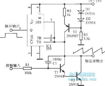
The oscillator with adjustable duty cycle
Published:2013/3/7 2:36:00 Author:Ecco | Keyword: oscillator , adjustable duty cycle
The oscillator with adjustable duty cycle is shown as figure.
(View)
View full Circuit Diagram | Comments | Reading(1073)
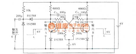
Broadband multivibrator
Published:2013/3/7 2:34:00 Author:Ecco | Keyword: Broadband multivibrator
Broadband multivibrator is shown as figure.
(View)
View full Circuit Diagram | Comments | Reading(894)
Venturi sine wave oscillator circuit
Published:2013/3/7 2:26:00 Author:Ecco | Keyword: Venturi , sine wave , oscillator
Venturi sine wave oscillator circuit is shown as figure.
(View)
View full Circuit Diagram | Comments | Reading(988)
Wien Bridge sinusoidal oscillator
Published:2013/3/7 2:27:00 Author:Ecco | Keyword: Wien Bridge , sinusoidal oscillator
Wien Bridge sinusoidal oscillator is shown as figure.
(View)
View full Circuit Diagram | Comments | Reading(978)
| Pages:12/195 1234567891011121314151617181920Under 20 |
Circuit Categories
power supply circuit
Amplifier Circuit
Basic Circuit
LED and Light Circuit
Sensor Circuit
Signal Processing
Electrical Equipment Circuit
Control Circuit
Remote Control Circuit
A/D-D/A Converter Circuit
Audio Circuit
Measuring and Test Circuit
Communication Circuit
Computer-Related Circuit
555 Circuit
Automotive Circuit
Repairing Circuit