
Signal Processing
Index 4
Shenlong fukang lighting and signal circuit diagram
Published:2013/12/25 19:27:00 Author: | Keyword: Shenlong fukang lighting and signal circuit diagram,
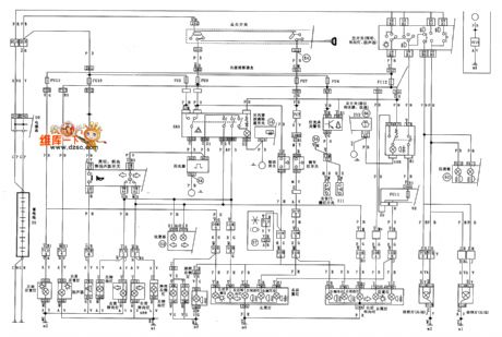
Shenlong fukang lighting and signal circuit diagram as shown below:
(View)
View full Circuit Diagram | Comments | Reading(1041)
Shenlong fukang interior lighting system circuit diagram
Published:2013/12/25 19:26:00 Author: | Keyword: Shenlong fukang interior lighting system circuit diagram,
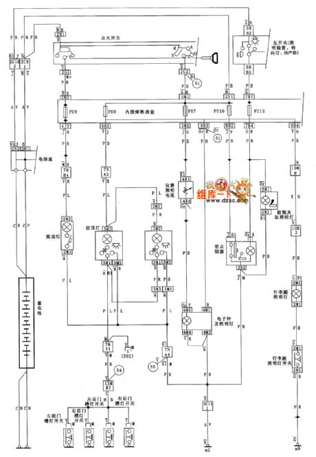
Shenlong fukang interior lighting system circuit diagram as shown below:
(View)
View full Circuit Diagram | Comments | Reading(854)
Shenlong fukang wiper and defrosting system circuit diagram
Published:2013/12/25 19:24:00 Author: | Keyword: Shenlong fukang wiper and defrosting system circuit diagram,
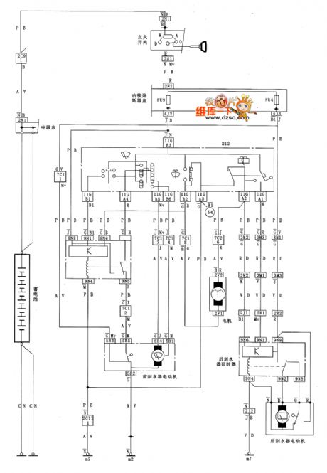
Shenlong fukang wiper and defrosting system circuit diagram as shown below:
(View)
View full Circuit Diagram | Comments | Reading(792)
Shenlong fukang defrosting system circuit diagram
Published:2013/12/25 19:23:00 Author: | Keyword: Shenlong fukang defrosting system circuit diagram,
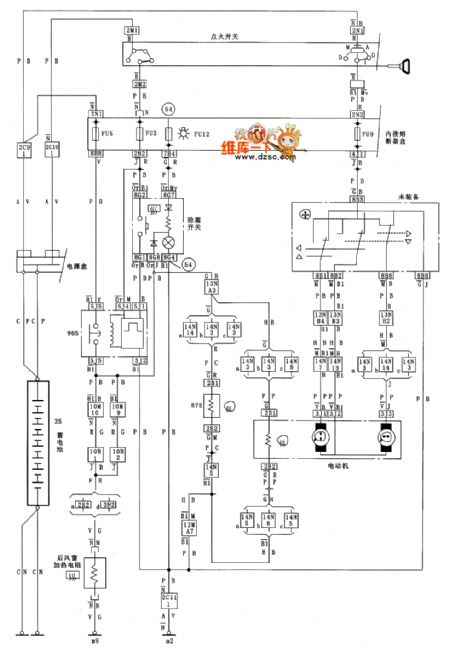
Shenlong fukang defrosting system circuit diagram as shown below:
(View)
View full Circuit Diagram | Comments | Reading(790)
Shenlong fukang central door lock circuit diagram and electric Windows
Published:2013/12/25 19:20:00 Author: | Keyword: Shenlong fukang central door lock circuit diagram and electric Windows,
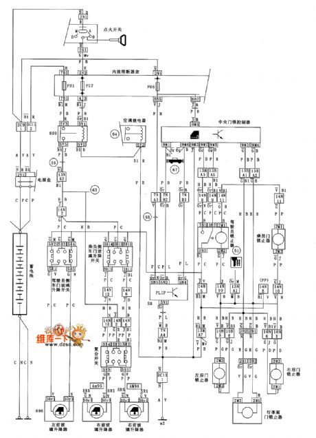
Shenlong fukang central door lock and electric Windows circuit diagram as shown below:
(View)
View full Circuit Diagram | Comments | Reading(870)
Shenlong fukang air conditioner circuit diagram
Published:2013/12/24 20:15:00 Author: | Keyword: Shenlong fukang air conditioner circuit diagram,
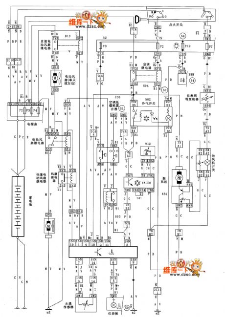
Shenlong fukang air conditioner circuit diagram as shown below:
(View)
View full Circuit Diagram | Comments | Reading(939)
Shenlong fukang anti-lock braking system (ABS) circuit diagram
Published:2013/12/24 20:12:00 Author: | Keyword: Shenlong fukang anti-lock braking system (ABS) circuit diagram,
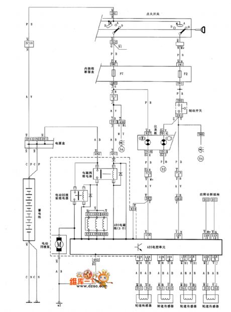
Shenlong fukang anti-lock braking system (ABS) circuit diagram as shown below:
(View)
View full Circuit Diagram | Comments | Reading(932)
Wing tiger 2005 electric rearview mirror circuit diagram
Published:2013/12/17 2:00:00 Author: | Keyword: Wing tiger 2005 electric rearview mirror circuit diagram,
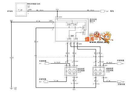
Wing tiger 2005 electric rearview mirror circuit diagram as shown below:
(View)
View full Circuit Diagram | Comments | Reading(1041)
Wien bridge RC oscillator circuit
Published:2013/12/12 20:10:00 Author:lynne | Keyword: Wien bridge RC oscillator circuit,

Wien bridge RC oscillator circuit shown in Figure:
(View)
View full Circuit Diagram | Comments | Reading(1150)
Alto power start, ignition, heater, washing and wiper circuit diagrams
Published:2013/12/9 21:09:00 Author:lynne | Keyword: Alto power start, ignition, heater, washing and wiper circuit diagrams,
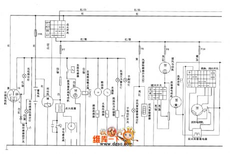
Alto power start, ignition, heater, washing and wiper circuit diagram is shown below:
(View)
View full Circuit Diagram | Comments | Reading(1095)
Alto steering, hazard warning lights, headlight washing and schematics
Published:2013/12/9 21:00:00 Author:lynne | Keyword: Alto steering, hazard warning lights, headlight washing and schematics
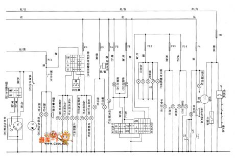
Alto steering, hazard warning lights, headlamp wash and circuit diagram is shown below:
(View)
View full Circuit Diagram | Comments | Reading(1036)
Alto air conditioning circuit diagram
Published:2013/12/9 20:54:00 Author:lynne | Keyword: Alto air conditioning circuit diagram,
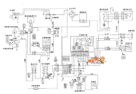
Alto air conditioning circuit diagram is shown below:
(View)
View full Circuit Diagram | Comments | Reading(1251)
Citroen TU3F2K engine schematics
Published:2013/12/9 20:52:00 Author:lynne | Keyword: Citroen TU3F2K engine schematics,

Citroen TU3F2K engine circuit diagram is shown below:
(View)
View full Circuit Diagram | Comments | Reading(971)
Citroen TU5JPK engine schematics
Published:2013/12/9 20:49:00 Author:lynne | Keyword: Citroen TU5JPK engine schematics,

Citroen TU5JPK engine circuit diagram is shown below:
(View)
View full Circuit Diagram | Comments | Reading(1147)
Simple Square Wave Generator with 7400
Published:2013/12/1 20:28:00 Author:lynne | Keyword: Simple Square Wave Generator
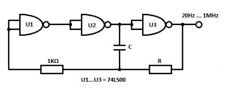
This is a very simple square wave generator circuit built with IC 74LS00 that can generate square signals with frequencies between 20 Hz and 1 MHz. Its stability is good enough for most applications. The output freq. is dimensioned through the RC components and time delay of the 3 inverter gates. The time delay of a logic gate is the elapsed time between a change of input state and the resulting change of the output state.To prevent the temperature and voltage supply from affecting the frequency of the square wave generator, the oscillator freq. fo must be smaller than 1/2tpn where:
tp = average delay time of each gaten = the number of gates
The above described oscillator has a tp of 10ns and n-3. The freq. is therefore:
fo << 1/2tpn = 1/2*10ns*3 = 16.6MHz
The voltage at the gate inputs varies from about _6V to -4V. The oscillation freq. can be made variable by using a 2.2KΩ potentiometer for R.
Square wave generator circuit schematic
(View)
View full Circuit Diagram | Comments | Reading(1392)
Rain Sound Generator-Sleep Aid in Case of Insomnia
Published:2013/11/11 19:23:00 Author:lynne | Keyword: Rain Sound Generator
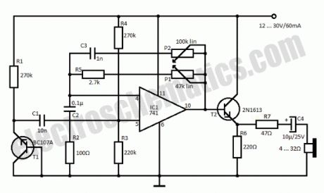
Insomnia treatment consist mostly of sleeping pills consumption but this circuit is an alternative for that and consists of a simple circuitry that generates a rain sound effect. The japanese researches were the first to discover that sound of rain has a relaxing effect. With the help of this simple circuit we can generate the rain sound which can be a sleep aid in case of insomnia.T1 is used as a noise generator and its signal is amplified by the 741 IC and thru T2, R7 and C4 goes to a headset with low resistance. If you do not want to use the headphones then use a speaker with impedance between 4 and 16 Ω. With the help of P1 can adjust sound level and with P2 the tone.
Schematic of Rain Sound Generator Circuit
(View)
View full Circuit Diagram | Comments | Reading(2962)
Photoelectric Smoke Detector
Published:2013/9/26 20:22:00 Author:lynne | Keyword: Photoelectric Smoke Detector

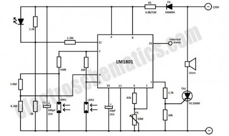
This photoelectric smoke detector circuit uses one LED and 2 LDRs to detect the smoke and sound an alarm. The LM1801 IC is the best choice for this circuit because we need a few external components and is used in almost any smoke alarm.
The whole photoelectric smoke detector circuit is powered from the 220V mains supply. D1 regulates the voltage, R1 decreases it until a proper level for the IC. C1 capacitor is filtering this voltage that is then stabilized with the zener diode inside LM1801.
Physically, the LDRs must be installed so that the smoke particles reflects the light from the LED on LDR2, causing decrease in its resistance. When there is smoke between the LED and LDRs the IC switches the thyristor Th1 which activates the siren.
The most difficult part in constructing this photoelectric smoke detector is to placement of LED and LDRs. Basically, the LED must be positioned exactly midway between the 2 LDRs, making sure there is no air flow between LED and LDR1. This can be accomplished by placing a transparent box around LDR1 and LED.The whole circuit sensitivity is adjustable with P1.
(View)
View full Circuit Diagram | Comments | Reading(1529)
Infrared Model Train Detector
Published:2013/8/22 20:13:00 Author:lynne | Keyword: Infrared Model Train Detector
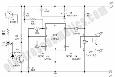
This simple and economical IR model train detector circuit is intended especially for those hobbyists who wish to add a smart sensor to detect trains on their model railway track. As can be seen in the schematic diagram, it comprises of a simple infrared transmitter and receiver wired around the good old PLL Tone Decoder LM567(IC1). It has a working range of around 10 to 50 cm. Output of the detector is galvanically isolated with the help of a standard opto-coupler CNY18-2 (IC2), which can be suitably interfaced to any external circuit for further processing task(s).
Working of the circuit is straight forward. When light from Infrared sender (D1) is relected by the wagon of the model train, IC1 through Infrared photo sensor (D2) receives the recovered signal at its input point (pin3). If PLL (IC1) is locked, its output (at pin8) drops low, thus disabling the optocoupler IC2 for the specific time and this process repeats based on the number of wagons.
Infrared componets D1 and D2 should be mounted such that D2 can only pick up reflected light. When a train passes, the infrared light is reflected at certain intervals, which produces a sort of ‘pulse code’ for the train. Using an external circuit connected through IC2, it is possible to distinguish various model trains from each other using the pulse code! The choice of D1 and D2 is not very critical, but they must be band compatible. Operating point of the detector is dependent on refleted light levels and value of the resistor R2 (here 22K) may need to be ‘tuned’ for optimum performance. (View)
View full Circuit Diagram | Comments | Reading(1958)
Electrical Live Wire Detector
Published:2013/8/21 21:46:00 Author:lynne | Keyword: Electrical Live Wire Detector
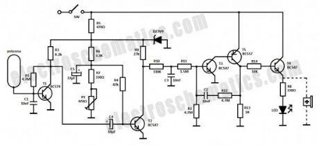
This circuit can detect only electrical wires connected to the mains (live wire). It has an LED for visual signalization and a buzzer for audio. As the electrician places the detector closer to the electrical wire the LED will flash at a higher frequency.
As you can see the schematic of the wire detector circuit is quite simple. The first stage has the antenna in base of T1; capacitor C1 is used for filtering parasite high frequency signals which are captured by the antenna.
The low freq signal is captured through C4 and is applied to the amplifier stage (T2) and then to the pulse shape filter made with R10, R11, C3 and T3, T4 and T5. The final stage (T5) is a current amplifier for the LED or you can place a buzzer too.
The antenna is a pcb loop that look like in the schematic with length of 50 mm and width of 20 mm. The trace width has 4 mm. (View)
View full Circuit Diagram | Comments | Reading(1787)
RF Spy Bug Detector Circuit
Published:2013/8/21 21:44:00 Author:lynne | Keyword: RF Spy Bug Detector Circuit
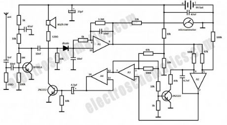
Here is a simple RF bug detector that will help you detect spy bugs and can operate up to 2 GHz. Below are some essential things required for this circuit:
to cover a large frequency band
make a sound during the detection
optical and acustical indication when near the bug
sensitivity not too high in order to accurately locate the rf bug
consume as little current from battery
A1, A2, A3, A4 = 1 x LM358 or CRX423 (14 pin types)
It can detect any RF waves with frequencies up to 2 GHz due to antenna circuitry and to input amplifier stage that is made of BFR91A transistor. The amplification is pretty high because of the way the base is polarised. The RF signal detection is made with a Schottky diode that has a low voltage on junction and is operating at a high frequency.
Further, the obtained voltage is filtered and amplified with A1. Its value is enough to be displayed on the scale of a microammeter. A2 and A3 sections together with the other components form a voltage controlled oscillator. The sound is amplified by A4 section and then is applied to a 8Ω/0.5W speaker. Use a telescopic antenna that can retract to a small length (~10cm) and can extend up to 1 meter. (View)
View full Circuit Diagram | Comments | Reading(1951)
| Pages:4/195 1234567891011121314151617181920Under 20 |
Circuit Categories
power supply circuit
Amplifier Circuit
Basic Circuit
LED and Light Circuit
Sensor Circuit
Signal Processing
Electrical Equipment Circuit
Control Circuit
Remote Control Circuit
A/D-D/A Converter Circuit
Audio Circuit
Measuring and Test Circuit
Communication Circuit
Computer-Related Circuit
555 Circuit
Automotive Circuit
Repairing Circuit