
Signal Processing
Index 9
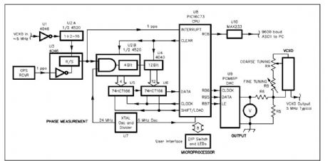
GPS-based frequency standard 3
Published:2013/5/14 22:10:00 Author:muriel | Keyword: GPS-based frequency standard
View full Circuit Diagram | Comments | Reading(923)
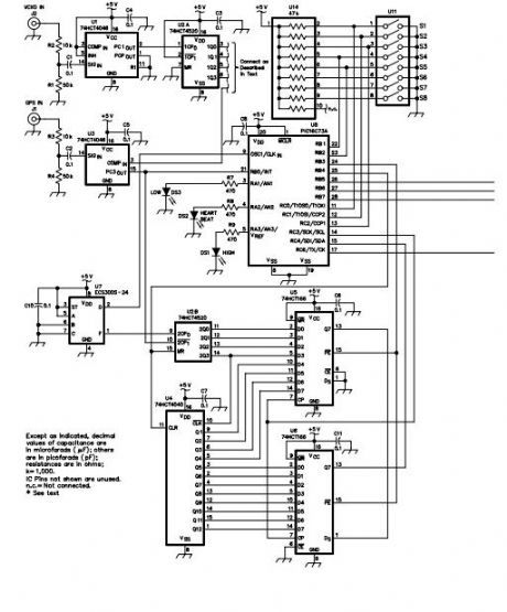
GPS-based frequency standard 2
Published:2013/5/14 22:09:00 Author:muriel | Keyword: GPS-based frequency standard
View full Circuit Diagram | Comments | Reading(914)
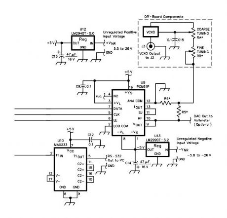
GPS-based frequency standard
Published:2013/5/14 22:08:00 Author:muriel | Keyword: GPS-based frequency standard
View full Circuit Diagram | Comments | Reading(1003)
Filter Circuit for the Earthworm Seismic Data Acquisition System
Published:2013/5/14 22:01:00 Author:muriel | Keyword: Filter Circuit, Earthworm Seismic Data , Acquisition System

View full Circuit Diagram | Comments | Reading(923)
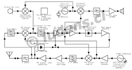
The synthesized exciter
Published:2013/5/9 21:25:00 Author:muriel | Keyword: The synthesized exciter

View full Circuit Diagram | Comments | Reading(1041)
80 Watt FM stereo broadcast transmitter
Published:2013/5/9 21:25:00 Author:muriel | Keyword: 80 Watt, FM , stereo broadcast transmitter
View full Circuit Diagram | Comments | Reading(1055)
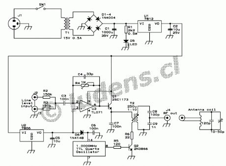
Small AM transmitter
Published:2013/5/9 21:24:00 Author:muriel | Keyword: Small AM transmitter
View full Circuit Diagram | Comments | Reading(953)
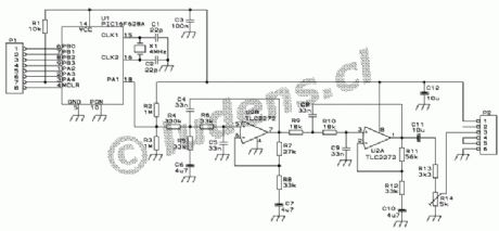
FTS-8 subtone encoder
Published:2013/5/9 21:19:00 Author:muriel | Keyword: FTS-8 subtone encoder
View full Circuit Diagram | Comments | Reading(1306)
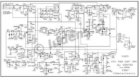
A 40 meter SSB QRP transceiver 2
Published:2013/5/9 21:17:00 Author:muriel | Keyword: 40 meter SSB, QRP transceiver
View full Circuit Diagram | Comments | Reading(2298)
A 40 meter SSB QRP transceiver
Published:2013/5/9 21:16:00 Author:muriel | Keyword: 40 meter , SSB QRP transceiver
View full Circuit Diagram | Comments | Reading(1543)
ULTRA LOW FREQUENCY RECEIVER
Published:2013/5/7 21:37:00 Author:muriel | Keyword: ULTRA LOW FREQUENCY RECEIVER
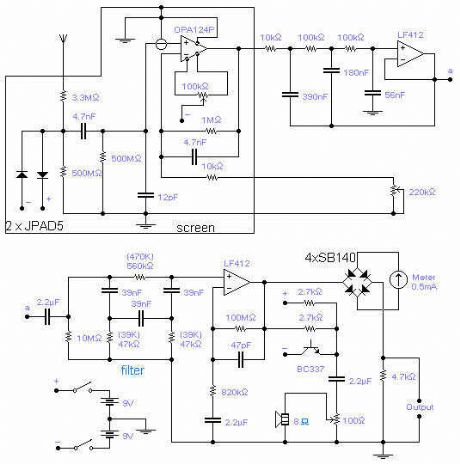
The frequency covered is from 0.1Hz to 10Hz and useful signals are received up to 16Hz. The first Op-Amp, properly shielded, must be installed close to the antenna (1-3m long) and connected to the rest of the circuit with a 5-core shielded cable. Adjust the 100k trimmer so that the DC setting at the output of the OPA124 does not change when turning the 220k sensitivity pot. A low pass filter followed by a notch filter take care of the mains induced noise. The values in brackets are good for a 60Hz mains. 1% components should be used for the 3 resistors and 3 capacitors of the notch filter. A voltage controlled oscillator gives an audible frequency that follows the input signal and it is very handy if the unit is made portable although I found that just walking around is enough to bury the signal being received. The output signal goes first to a meter and then is available for the connection to a data logger, which is an almost essential part of the receiver. Sensitivity is quite adequate: any TV set switching on in the area will be detected. There are also a host of other mysterious signals of unknown origin. The input protection diodes are special low leakage type and should not be replaced by standard diodes. These diodes can be dispensed with if the antenna is installed with care and away from strong electric fields. The diodes connected to the meter are Schottky diodes and will provide a bias against very small signals (mostly noise) which will not go through to the data logger. Pin connection for OPA124: 1 and 5: DC set, 2 and 3: inverting and non-inverting, 6: output, 8: substrate. Pin connection for LF412: 2 and 3: inverting and non-inverting, 1: output, 6 and 5: inverting and non-inverting, 7: output. (View)
View full Circuit Diagram | Comments | Reading(2064)
Butterworth filter has adjustable group delay
Published:2013/4/18 3:00:00 Author:muriel | Keyword: Butterworth filter, adjustable group , delay
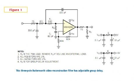
This Sallen-Key realization of a 5.25-MHz, three-pole Butterworth filter has a gain of 2V/V and can drive 75Ω back-terminated coax with an overall gain of 1 .It can used to reconstruct component-video (Y, Pb, Pr) and RGB signals, this filter has an insertion loss greater than 20 db at 13.5 MHz and greater than 40 db at 27 MHz . Like the antialiasing filter before an ADC, this filter removes the higher frequency replicas of a signal following a DAC. To preserve quality in the video waveform, you should minimize group-delay variations in the filter and any group-delay differential between filters. (View)
View full Circuit Diagram | Comments | Reading(1441)
Audio / Signal Processing
Published:2013/4/18 1:58:00 Author:muriel | Keyword: Audio, Signal , Processing
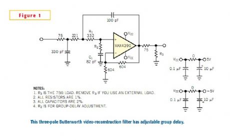
This Sallen-Key realization of a 5.25-MHz, three-pole Butterworth filter has a gain of 2V/V and can drive 75Ω back-terminated coax with an overall gain of 1 .It can used to reconstruct component-video (Y, Pb, Pr) and RGB signals, this filter has an insertion loss greater than 20 db at 13.5 MHz and greater than 40 db at 27 MHz . Like the antialiasing filter before an ADC, this filter removes the higher frequency replicas of a signal following a DAC. To preserve quality in the video waveform, you should minimize group-delay variations in the filter and any group-delay differential between filters.source (View)
View full Circuit Diagram | Comments | Reading(1175)
Sferic Signal Simulator circuit
Published:2013/3/28 4:13:00 Author:Ecco | Keyword: Sferic Signal Simulator

Sferic signal simulator is used to produce an impulse signal which simulates the waveform of a sferic, a radio atmospheric signals produced by a lightning strike. In time domain, the waveform of a sferic signal is a single high amplitude spike. When this pulse is analyzed in frequency domain, it will show a wide band spectrum ranging from few kilohertz to several tens of kilohertz. Here is the schematic diagram of the sferic signal simulator circuit:
(View)
View full Circuit Diagram | Comments | Reading(992)
The Wien-Bridge Oscillator Using HA2541 Op-Amp
Published:2013/3/28 3:53:00 Author:Ecco | Keyword: Wien-Bridge Oscillator , Op-Amp
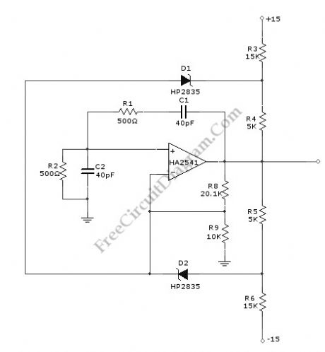
A Wien-Bridge oscillator circuit can be built from HA2541 and some basic components. This circuit can generate good-quality sine wave of 40 MHz with an upper limit of 50 MHz. The R3 through R7 and D2 and D1 provide the diode limiting for this circuit. Here is the schematic diagram of this circuit:
(View)
View full Circuit Diagram | Comments | Reading(1542)
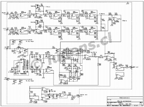
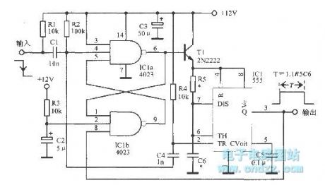
Ultra-long period multivibrator
Published:2013/3/27 3:28:00 Author:Ecco | Keyword: Ultra-long period multivibrator
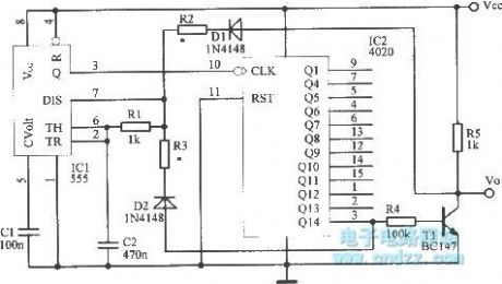
Ultra-long period multivibrator is shown as figure.
(View)
View full Circuit Diagram | Comments | Reading(1144)
28.3MHz third harmonic TrL oscillator
Published:2013/3/28 1:53:00 Author:Ecco | Keyword: 28.3MHz, third harmonic , TrL oscillator
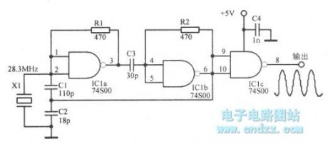
28.3MHz third harmonic TrL oscillator is shown as figure.
(View)
View full Circuit Diagram | Comments | Reading(1368)
455Hz oscillator circuit
Published:2013/3/27 3:26:00 Author:Ecco | Keyword: 455Hz , oscillator
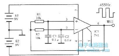
455Hz oscillator circuit is shown as figure.
(View)
View full Circuit Diagram | Comments | Reading(1147)
Integrated power oscillator
Published:2013/3/27 3:27:00 Author:Ecco | Keyword: Integrated power oscillator
Integrated power oscillator is shown as figure.
(View)
View full Circuit Diagram | Comments | Reading(1102)
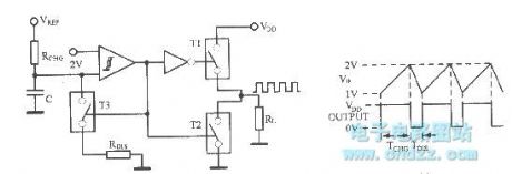
Micro- pending power square wave generating circuit
Published:2013/3/28 1:58:00 Author:Ecco | Keyword: Micro- pending power, square wave, generating
Micro- pending power square wave generating circuit is shown as figure.
(View)
View full Circuit Diagram | Comments | Reading(955)
| Pages:9/195 1234567891011121314151617181920Under 20 |
Circuit Categories
power supply circuit
Amplifier Circuit
Basic Circuit
LED and Light Circuit
Sensor Circuit
Signal Processing
Electrical Equipment Circuit
Control Circuit
Remote Control Circuit
A/D-D/A Converter Circuit
Audio Circuit
Measuring and Test Circuit
Communication Circuit
Computer-Related Circuit
555 Circuit
Automotive Circuit
Repairing Circuit