
555 Circuit
Index 47
Changan starter generator and ignition system circuit diagram
Published:2011/4/1 2:16:00 Author:Rebekka | Keyword: Changan starter, ignition system , generator system
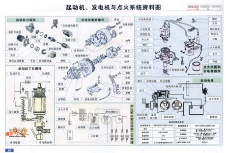
Changan starter generator and ignition system circuit diagram is shown as below.
(View)
View full Circuit Diagram | Comments | Reading(2300)
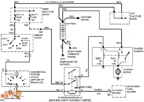
Kai Tai Lake starting system circuit diagram
Published:2011/4/1 2:16:00 Author:Rebekka | Keyword: Kai Tai Lake starting system
View full Circuit Diagram | Comments | Reading(638)
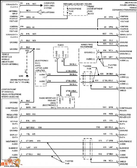
Kai Tai Lake vehicle communications circuit diagram
Published:2011/4/1 2:17:00 Author:Rebekka | Keyword: Kai Tai Lake vehicle communications
View full Circuit Diagram | Comments | Reading(616)
Kai Tai Lake oxygen sensor circuit diagram
Published:2011/4/1 2:18:00 Author:Rebekka | Keyword: Kai Tai Lake oxygen sensor
View full Circuit Diagram | Comments | Reading(696)
Cadillac throttle circuit diagram
Published:2011/4/1 2:22:00 Author:Rebekka | Keyword: Cadillac throttle
View full Circuit Diagram | Comments | Reading(543)
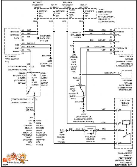
Ford focus rear bumper circuit diagram
Published:2011/4/1 22:48:00 Author:Rebekka | Keyword: Ford focus rear bumper
Ford focus rear bumper circuit diagram is shown as below.
(View)
View full Circuit Diagram | Comments | Reading(631)
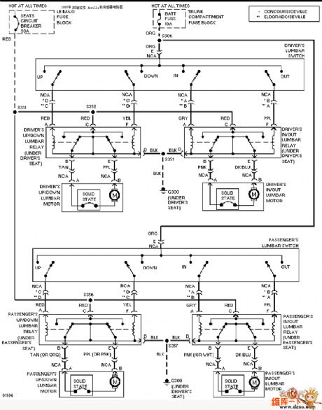
The power window circuit of Shanghai GM Cadillac XLR car
Published:2011/4/1 3:32:00 Author:Joan | Keyword: Shanghai GM , Cadillac XLR car , power window
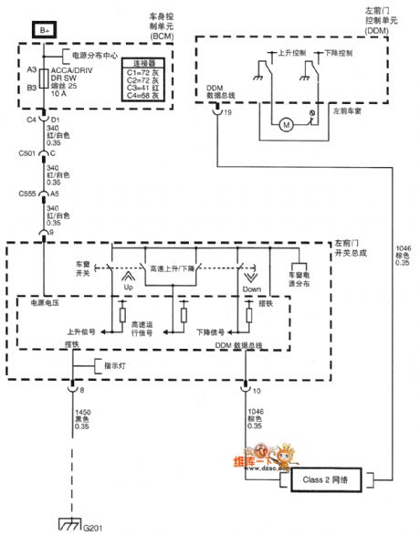
The power window circuit of Shanghai GM Cadillac XLR car (View)
View full Circuit Diagram | Comments | Reading(1045)
555 Timing control circuit diagram
Published:2011/3/30 21:31:00 Author:Ecco | Keyword: Timing control
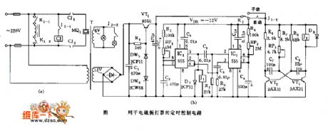
555 Timing control circuit diagram is as below:
(View)
View full Circuit Diagram | Comments | Reading(733)
555 touching timing switch circuit diagram
Published:2011/3/27 21:42:00 Author:Ecco | Keyword: 555 touching timing switch
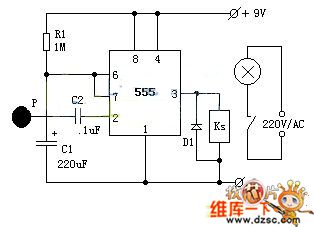
The integrated circuit IC1 is a piece of 555 timing circuit, connected to monostable circuit here. Usually as there's no induced voltage in the port of touching slab P, after the capacitance C1 passes 555 NO.7 pin to discharge, the outputof NO.3 pin is in low level, relay KS continue to release, the lamp won't be lighted.
While needing to turn on a lamp, to touch sheet metal P by hand, the human body's flooding wave signal voltage is applied into 555 triggering ports by C2, and makes 555 output change from low level to high level, the relay KS pulls in, the lamp will be turned on. At the same time, the interior of 555 NO. 7 pin stops working, the power supply then charges for C1 by R1, this is the periodic begin.When the voltage of C1 goes uo to 2/3 of power supply, 555 NO. 7 pin make C1 diacharge until NO. 3 pin is in low level again from high level, the relay releases, the lamp is turned off, this is the periodic over. (View)
View full Circuit Diagram | Comments | Reading(911)
Uninterruptible Power Supply Battery Voltage Monitor Circuit Diagram
Published:2011/3/21 0:46:00 Author:Joan | Keyword: Uninterruptible Power Supply, Battery Voltage Monitor
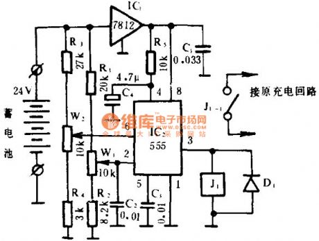
The Uninterruptible Power Supply is commonly used to convert the battery voltage to 220V power supply in the power cut. The monitor can monitor battery voltage state when high or low, and charge circuit on and off automatically, which ensure enough storage battery to extend life.
As the following diagram shown, IC2 (555) is connected in a bistable mode, R3, W2, R4, and R1, W1, R2 voltage networks are grouped into upper and lower sampling circuits. respectively, the threshold is added to 555 Threshold end and Trigger-side. When the battery makes pin 2 below 1/3 VDD, the 555 sets, J1 pulls, the charge circuit connects to charge; when the battery is charged high enough, the voltage of pin 6 is higher than 2/3 VDD, 555 resets and automatic disconnects the charging circuit, so that the battery voltage is maintained in a certain voltage range.
Thefollowing diagram is Uninterruptible Power Supply Battery Voltage Monitor Circuit Diagram.
(View)
View full Circuit Diagram | Comments | Reading(1631)
| Pages:47/47 At 2041424344454647 |
Circuit Categories
power supply circuit
Amplifier Circuit
Basic Circuit
LED and Light Circuit
Sensor Circuit
Signal Processing
Electrical Equipment Circuit
Control Circuit
Remote Control Circuit
A/D-D/A Converter Circuit
Audio Circuit
Measuring and Test Circuit
Communication Circuit
Computer-Related Circuit
555 Circuit
Automotive Circuit
Repairing Circuit