
555 Circuit
Index 42
555 refrigerator protection circuit 1
Published:2011/4/25 22:57:00 Author:Ecco | Keyword: 555 , refrigerator , protection
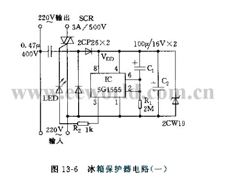
The circuit is shown in Figure 13-6, the circuit is based on 555circuit to form power delay protection circuit. The connection of C1 makes pin 6 be in high level, and pin 3 be in low level when the power failure and supply again, SCR is cut off.
C1 charges, so the pin 2 is lower than the trigger time of 1/3 vdd, that is the delay time td.
Icon corresponding td parameter is about 6 minutes. Setting to 55, pin 3 outputs high level. SCR turns on, the refrigerator gets power and the working indicator LED is lit.
(View)
View full Circuit Diagram | Comments | Reading(966)
555 darkroom timer circuit 3
Published:2011/4/25 22:55:00 Author:Ecco | Keyword: 555, darkroom , timer circuit

As the figure 17-16 shown, the timing circuit is composed of two branches of 555, IC1 forms a timer, IC2 is a second signal metronome. AN1 is the timer button, clicking the AN1, 555 sets, J pulls in, light exposure lamp H1 is lit, safelight H2 is off. K1 is regular file, when the C1 (or C2) is charged to more than 2/3 threshold level, the 555 resets, J releases. H1 is off, H2 is lit, exposure ended. IC2 and RP2, R4, R5, C4 etc. form astable multivibrator, adjusting the RP2 make the oscillation be 1Hz. The output of drives red LED light by VT1.
(View)
View full Circuit Diagram | Comments | Reading(894)
555 Timekeeping audio circuit
Published:2011/4/25 22:18:00 Author:Ecco | Keyword: 555 , Timekeeping , audio circuit
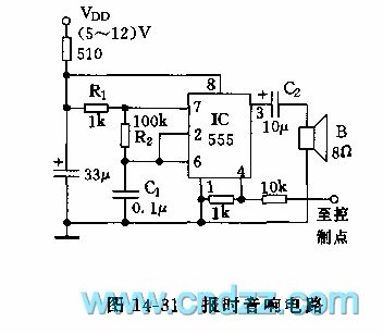
The circuit is shown in Figure 14-31, it is a timing signal controlled multivibrator composed of 555. Pin 4 of 555 is the force reset terminal, when the pin voltage drops below 0.4V, the circuit will go to non-trigger state. Using the foot control to external timing signals, usually it shows a low potential, while the voltage of time signal being higher than 1V, the circuit turns and issues an audio time signal with about 400Hz. Pin 4 of 555 is connected to the output clock timing, or connected to the security and other sensing devices deflection point by a 10kΩ resistor. Once there is a high mutation, the speaker will issue a hasty sound, the parameters of oscillator can be changed by the R1, R2, C1.
(View)
View full Circuit Diagram | Comments | Reading(692)
Circuit Diagram of 555 Inductive-Switch Power Supplier
Published:2011/4/21 1:32:00 Author:Tina | Keyword: Inductive-Switch, Power Supplier
The figure as shown, 555 and R1、R2、C1 build up the astable multivibrator, the oscillation frequency is about 10KHZ, the duty cycle is nearly 50%. VT2、VT3 are used as the switch to amplify the current. When the oscillating square wave is high, VT2, VT3 will be conduction and then discharge to the LC; when the current is low, the energy storage of L supply power to the burden by the freewheeling diode circuit. When the condition is overvoltage, DW will breakdown and VT1 conduction saturated, C<0.7V, this process play the fuction of regulator and dynamic balance.
Welcome to reprint, the information is from the Weiku Electronic Market Network (www.dzsc.com).
(View)
View full Circuit Diagram | Comments | Reading(569)
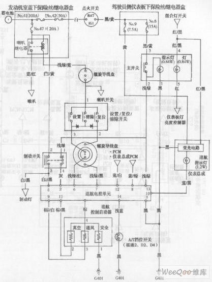
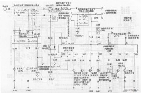
ACCORD combined meter circuit diagram
Published:2011/4/25 1:28:00 Author:Rebekka | Keyword: ACCORD, combined meter
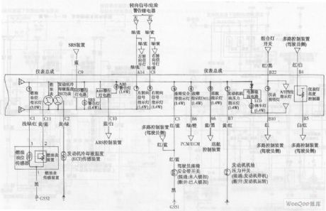
ACCORD combined meter circuit diagram is shown as above. (View)
View full Circuit Diagram | Comments | Reading(597)
ACCORD multiple control system circuit diagram
Published:2011/4/25 1:26:00 Author:Rebekka | Keyword: ACCORD, multiple control system
View full Circuit Diagram | Comments | Reading(557)
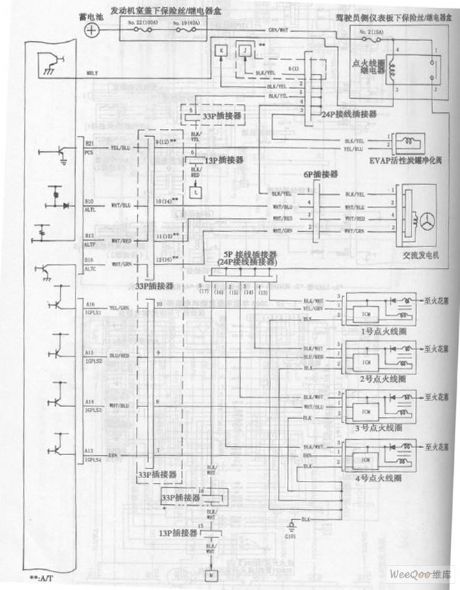
Accord Car navigation system circuit diagram
Published:2011/4/25 1:25:00 Author:Rebekka | Keyword: Accord car navigation system
View full Circuit Diagram | Comments | Reading(1003)
ACCORD combined meter circuit diagram 1
Published:2011/4/25 1:29:00 Author:Rebekka | Keyword: ACCORD, combined meter
ACCORD combined meter circuit diagram is shown as above. (View)
View full Circuit Diagram | Comments | Reading(589)
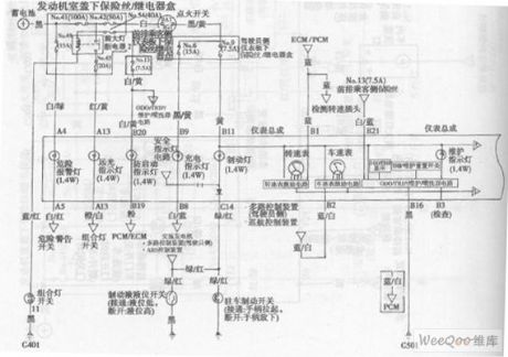
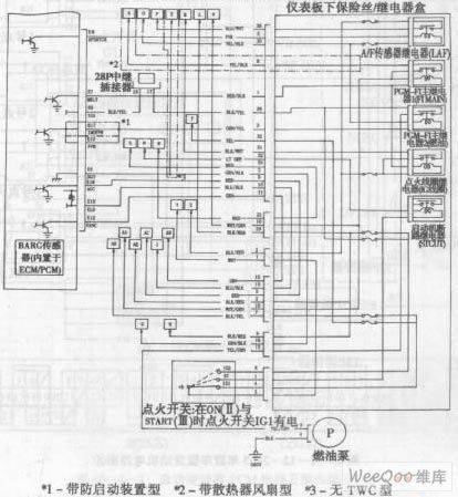
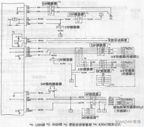
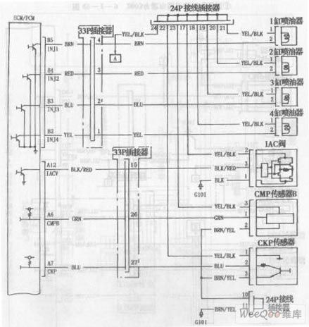
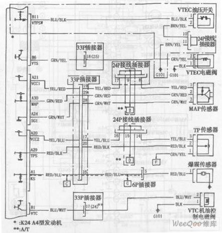
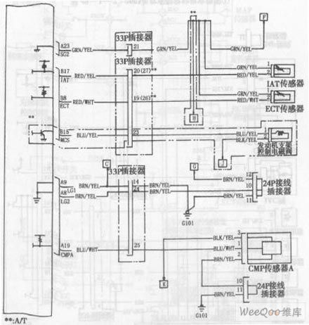
ACCORD 2003 models engine circuit diagram 6
Published:2011/4/25 1:36:00 Author:Rebekka | Keyword: ACCORD , 2003 models, engine
ACCORD 2003 models engine circuit diagram is shown as above. (View)
View full Circuit Diagram | Comments | Reading(535)
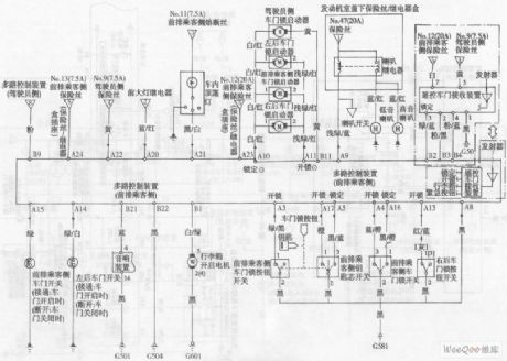
ACCORD anti-theft system circuit diagram 3
Published:2011/4/25 1:30:00 Author:Rebekka | Keyword: ACCORD , anti-theft system
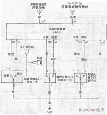
ACCORD anti-theft system circuit diagram is shown as above. (View)
View full Circuit Diagram | Comments | Reading(582)
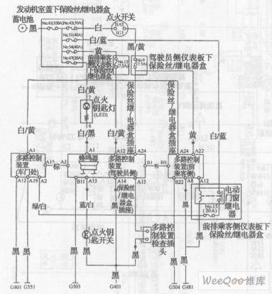
ACCORD anti-theft system circuit diagram 1
Published:2011/4/25 1:31:00 Author:Rebekka | Keyword: ACCORD, anti-theft system
ACCORD anti-theft system circuit diagram is shown as above. (View)
View full Circuit Diagram | Comments | Reading(574)
ACCORD anti-theft system circuit diagram 2
Published:2011/4/25 1:31:00 Author:Rebekka | Keyword: ACCORD , anti-theft system
View full Circuit Diagram | Comments | Reading(565)
ACCORD airbag system circuit diagram
Published:2011/4/25 1:32:00 Author:Rebekka | Keyword: ACCORD , airbag system
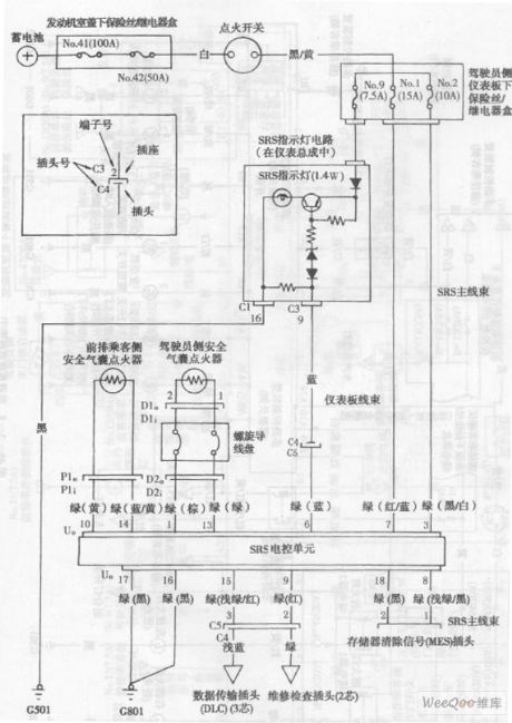
ACCORD airbag system circuit diagramis shown as above. (View)
View full Circuit Diagram | Comments | Reading(864)
ACCORD 2003 models engine circuit diagram 5
Published:2011/4/25 1:35:00 Author:Rebekka | Keyword: ACCORD , 2003 models , engine
ACCORD 2003 models engine circuit diagram is shown as above. (View)
View full Circuit Diagram | Comments | Reading(606)
ACCORD 2003 models engine circuit diagram 4
Published:2011/4/25 1:37:00 Author:Rebekka | Keyword: ACCORD , 2003 models , engine
ACCORD 2003 models engine circuit diagram is shown as above. (View)
View full Circuit Diagram | Comments | Reading(544)
ACCORD 2003 models engine circuit diagram 1
Published:2011/4/25 1:40:00 Author:Rebekka | Keyword: ACCORD , 2003 models , engine
ACCORD 2003 models engine circuit diagram is shown as above. (View)
View full Circuit Diagram | Comments | Reading(554)
ACCORD 2003 models engine circuit diagram 2
Published:2011/4/25 1:38:00 Author:Rebekka | Keyword: ACCORD , 2003 models , engine
ACCORD 2003 models engine circuit diagram is shown as above. (View)
View full Circuit Diagram | Comments | Reading(585)
ACCORD 2003 models engine circuit diagram 3
Published:2011/4/25 1:38:00 Author:Rebekka | Keyword: ACCORD, 2003 models , engine
ACCORD 2003 models engine circuit diagram is shown as above. (View)
View full Circuit Diagram | Comments | Reading(536)
Mitsubishi Pajero light off-road car circuit wiring harness circuit structure diagram
Published:2011/4/25 3:59:00 Author:Rebekka | Keyword: Mitsubishi Pajero, wiring harness

Mitsubishi Pajero light off-road car circuit wiring harness circuit structure diagram is shown as above. (View)
View full Circuit Diagram | Comments | Reading(5827)
The automatic refrigerator protection composed of 555
Published:2011/4/25 3:38:00 Author:Ecco | Keyword: automatic, refrigerator, protection , 555
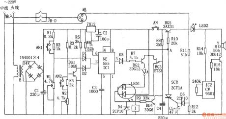
The chart shows the automatic refrigerator protection circuit. The protection is composed of the step-down circuit, undervoltage and overvoltage control circuit, delay circuit, leakage detection circuit and sound and light alarm circuit. Buck rectifier circuit provides DC voltage for the entire circuit. The protection has the functions of overvoltage and undervoltage protection, power delay, automatic power-off leakage, sound and light alarm and so on, thereby avoiding accidental damage caused to refrigerator.
(View)
View full Circuit Diagram | Comments | Reading(2378)
| Pages:42/47 At 2041424344454647 |
Circuit Categories
power supply circuit
Amplifier Circuit
Basic Circuit
LED and Light Circuit
Sensor Circuit
Signal Processing
Electrical Equipment Circuit
Control Circuit
Remote Control Circuit
A/D-D/A Converter Circuit
Audio Circuit
Measuring and Test Circuit
Communication Circuit
Computer-Related Circuit
555 Circuit
Automotive Circuit
Repairing Circuit