
Index 387
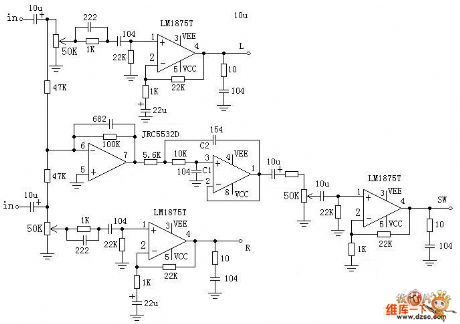
2.1 channel active speaker wiring diagram
Published:2011/6/30 3:06:00 Author:Ecco | Keyword: 2.1 channel , active , speaker, wiring
View full Circuit Diagram | Comments | Reading(3913)
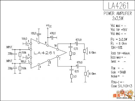
LA4261 audio IC circuit diagram
Published:2011/6/28 2:41:00 Author:Ecco | Keyword: audio IC
View full Circuit Diagram | Comments | Reading(1423)
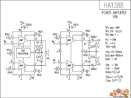
HA1388 audio IC circuit diagram
Published:2011/7/1 1:40:00 Author:Ecco | Keyword: audio IC
View full Circuit Diagram | Comments | Reading(1239)
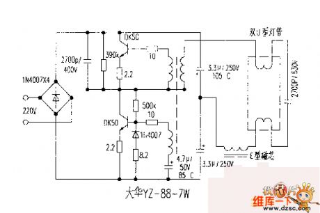
Dahua YZ-88-7W electronic ballast circuit diagram
Published:2011/7/1 1:52:00 Author:Ecco | Keyword: Dahua , electronic ballast
View full Circuit Diagram | Comments | Reading(1236)
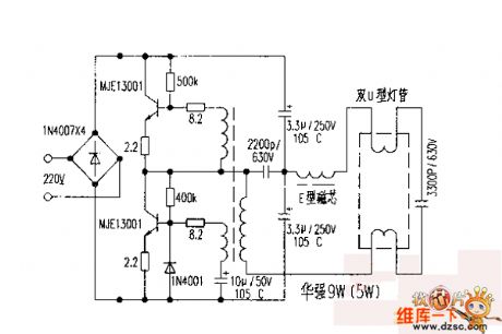
9 W (5 W) electronic ballast circuit diagram
Published:2011/7/1 1:57:00 Author:Ecco | Keyword: 9 W , 5 W , electronic ballast
View full Circuit Diagram | Comments | Reading(2418)
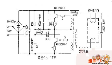
Rong Gan 13 electronic ballast circuit diagram
Published:2011/7/1 1:39:00 Author:Ecco | Keyword: Rong Gan 13 lectronic ballast
View full Circuit Diagram | Comments | Reading(1406)
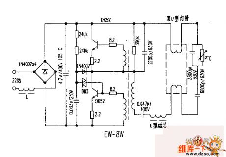
EW-8W electronic ballast circuit diagram
Published:2011/7/1 1:18:00 Author:Ecco | Keyword: electronic ballast
View full Circuit Diagram | Comments | Reading(2470)
In-phase addition circuit composed of the LF155
Published:2011/7/3 21:55:00 Author:Rebekka | Keyword: In-phase addition

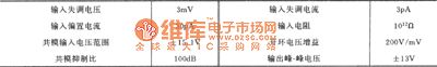
Themain parameters typical values of the LF155 are:
(View)
View full Circuit Diagram | Comments | Reading(493)
Discrete sound and light control stairs delay switch circuit(1)
Published:2011/6/29 20:19:00 Author:Ecco | Keyword: Discrete , sound , light , control , stairs, delay switch
Features: during the day, lights are automatically blocked off; in the evening, as long as someone on the stairs, the lights are lit and turned off in tens of seconds delay time. Circuit uses the two-wire system connection, and the switch only has two outside terminals, which can replace the ordinary switch without having to change the existing lighting circuit. In the figure, RL can select MG44, MG45 photosensitive resistors with great difference between light resistance and dark resistance; B should use small electret condenser microphone with higher sensitivity, such as CRZ2-113F type.
(View)
View full Circuit Diagram | Comments | Reading(487)
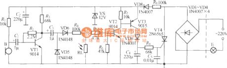
Discrete sound and light control stairs delay switch circuit(10)
Published:2011/6/30 0:51:00 Author:Ecco | Keyword: Discrete , sound , light, control, stairs delay switch
The sound and light control stairs delay switch circuit shown in the Figure uses the positive feedback audio amplifier, and it has higher sound control sensitivity, and at night, the general talking or footsteps can trigger the light E to emit light.
(View)
View full Circuit Diagram | Comments | Reading(440)
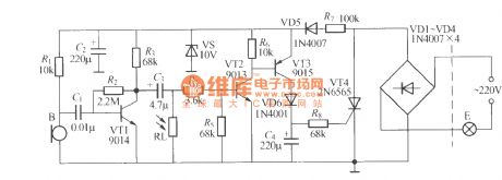
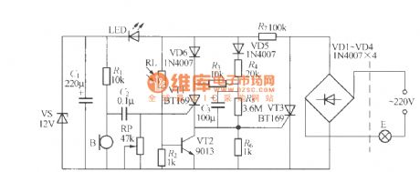
Discrete sound and light control stairs delay switch circuit(2)
Published:2011/6/30 1:05:00 Author:Ecco | Keyword: Discrete , sound , light , control, stairs delay switch
The improved sound and light control stairs delay switch circuit is shown as the chart, and it has higher sensitivity,and the reason is that the audio signal output by VT1 is doubler rectified by VD5, VD6 to turn into DC control voltage to trigger VT2, VT3 conduction, then VT4 is turned on, and light-emitting lamp E is lit. Circuit delay time is determined by the value of R9 and C4, and the time is typically tens of seconds. Capacitor C5 can absorb power grid interfere pulses to prevent false triggering.
(View)
View full Circuit Diagram | Comments | Reading(728)
Discrete sound and light control stairs delay switch circuit(4)
Published:2011/6/30 1:58:00 Author:Ecco | Keyword: Discrete, sound , light , control , stairs delay switch
View full Circuit Diagram | Comments | Reading(425)
Discrete sound and light control stairs delay switch circuit(5)
Published:2011/6/30 1:57:00 Author:Ecco | Keyword: Discrete, sound , light, control , stairs delay switch
The simple sound and light control stairs delay switch circuit shown as the chart with the slightly lower sensitivity, the general talking is sometimes difficult to trigger the circuit, but you can start the panel to open light by direct clapping slap switch.
(View)
View full Circuit Diagram | Comments | Reading(826)
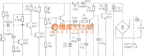
Discrete sound and light control stairs delay switch circuit(7)
Published:2011/6/30 1:29:00 Author:Ecco | Keyword: Discrete, sound, light, control , stairs delay switch
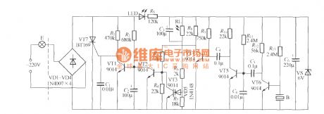
In the circuit: ①it adds a light-emitting diode LED, which can emit low-light at night to play indicating switch role; ② it increases the light control sensitivity adjusting resistor R7which can adjust the light control point; ③ The two ends of RL are connected a capacitor C3 in parallel to improve anti-jamming performance of light-control circuit; ④ the additional diode VD5 can improve circuit reliability; ⑤ VT2 and VT4 use direct coupling resistors to improve signal transmission efficiency.
(View)
View full Circuit Diagram | Comments | Reading(404)
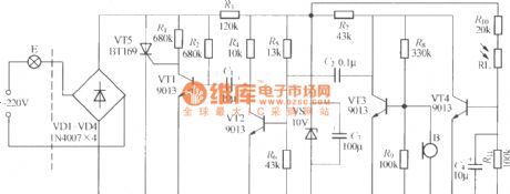
Discrete sound and light control stairs delay switch circuit(8)
Published:2011/6/30 1:22:00 Author:Ecco | Keyword: Discrete, sound , light , control, stairs delay switch
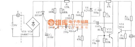
The sound and light control stairs delay switch circuit shown as the chart uses an improved piezoelectric ceramics for the sound -power transducer, and the circuit structure is relatively simple. The circuit delay time is determined by many factors, and the icon data delay time is 50s, which do not meet the requirements. C2 can increase or decrease the capacity to adjust. Adjusting R9 can adjus the light control point of the circuit.
(View)
View full Circuit Diagram | Comments | Reading(450)
Wireless remote control electric initiator 1
Published:2011/6/30 22:18:00 Author:Nicole | Keyword: wireless remote control, electric initiator
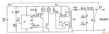
The wireless remote control electric initiator circuit is composed of wireless remote control transmitter and wireless receive initiation circuit. The wireless remote control transmitter uses finished product four keys micro remote control transmitter which contains TWH9236D module.
The wireless receive blaster circuit is made of power supply circuit, wireless receive control circuit, oscillation boost circuit and charge-discharge circuit, it is shown in the figure 8-26.
The power supply circuit consists of battery GB, power switch S(Sa, Sb), power indication LED VL and current limiting resistor R6.
The charge-discharge circuit is composed of resistors R4, R5, capacitors C1, C2, power switch S and K2's normally open contact.
(View)
View full Circuit Diagram | Comments | Reading(763)
Electrical blaster 1
Published:2011/6/28 2:25:00 Author:Nicole | Keyword: Electrical blaster
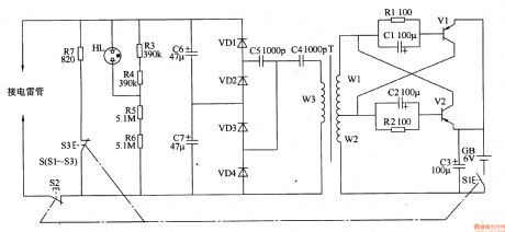
The electrical blaster circuit is composed of self-exciting oscillator, high voltage generation circuit, charge indication circuit and discharge circuit, it is shown in the figure 8-23.
The self-exciting oscillator circuit is made of resistors R1, R2, capacitors C1-C3, transistors V1, V2, charge switch S1, battery GB and W1, W2 windings of boost transformer T.
The high voltage generation circuit consists of W3 winding of boost transformer T, capacitors C4-C7 and rectifier diode VD1-VD4. The dual voltage rectifier circuit is made of C4, C5 and VD1-VD4.
The charge indication circuit is composed of resistors R3-R6 and neon indication light HL.
(View)
View full Circuit Diagram | Comments | Reading(763)
2CU301 silicon photosensitive diode appearance structure and circuit
Published:2011/7/3 20:49:00 Author:Christina | Keyword: silicon, photosensitive diode, appearance structure
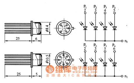
The 2CU301 four-quadrant silicon photosensitive diode is in the sealed metal shell package, there is the glass window on the top. The appearance structure is as shown in the figure.
Figure: 2CU301 silicon photosensitive diode appearance structure and circuit (View)
View full Circuit Diagram | Comments | Reading(536)
Electric welding machine no load electricity saver 12
Published:2011/6/30 22:00:00 Author:Nicole | Keyword: electric welding machine, electricity saver
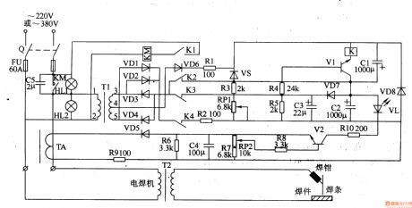
The electric welding machine no load electricity saver circuit is composed of current detection circuit, power supply circuit and switch control circuit, it is shown in the figure 8-16.
The current detection circuit is made of current transformer TA, rectifier diode VD5, transistor V2, potentiometer RP2 and some peripheral devices.
The power supply circuit consists of capacitor C5, power switch Q, signal transformer T1, rectifier diodes VD1-VD4, VD6, VD7, steady voltage diode VS and filter capacitors C1-C3.
The switch control circuit is composed of transistor V1, relay K and AC contactor KM.
(View)
View full Circuit Diagram | Comments | Reading(2999)
Electric welding machine no load electricity saver 11
Published:2011/6/30 21:54:00 Author:Nicole | Keyword: electric welding machine, electricity saver
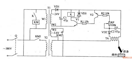
The electric welding machine no load electricity saver circuit is composed of knife switch Q, AC contactor KM, relay K, power transformer T1, electric welding machine transformer T2, transistors V1, V2, resistors R1, R2, capacitors C1, C2, potentiometer RP, diodes VD1-VD3 and current transformer TA, it is shown in the figure 8-15.
In the circuit, 24V DC power supply circuit is made of T1, VD, C1, the current detection control circuit consists of K, KM, Rl, R2, RP, C2, VD2, VD3 and TA.
V2's sensitivity can be changed by adjusting RP.
(View)
View full Circuit Diagram | Comments | Reading(4072)
| Pages:387/471 At 20381382383384385386387388389390391392393394395396397398399400Under 20 |
Circuit Categories
power supply circuit
Amplifier Circuit
Basic Circuit
LED and Light Circuit
Sensor Circuit
Signal Processing
Electrical Equipment Circuit
Control Circuit
Remote Control Circuit
A/D-D/A Converter Circuit
Audio Circuit
Measuring and Test Circuit
Communication Circuit
Computer-Related Circuit
555 Circuit
Automotive Circuit
Repairing Circuit