
Index 389
Current inductive circuit composed of the LP3945
Published:2011/7/1 1:03:00 Author:TaoXi | Keyword: Current inductive

View full Circuit Diagram | Comments | Reading(412)
LA3210 audio IC circuit
Published:2011/7/1 1:04:00 Author:TaoXi | Keyword: audio IC
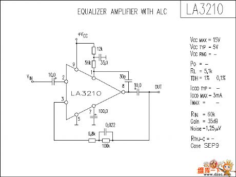
The LA3210 audio IC circuit is as shown in the figure:
(View)
View full Circuit Diagram | Comments | Reading(1993)
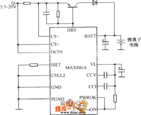
MAX846A typical application circuit
Published:2011/7/1 1:23:00 Author:TaoXi | Keyword: typical application
View full Circuit Diagram | Comments | Reading(461)
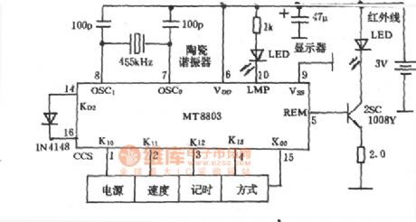
infrared emitter(MT8803) of electric fan circuit
Published:2011/6/30 2:20:00 Author:chopper | Keyword: infrared emitter, electric fan
View full Circuit Diagram | Comments | Reading(528)
TA8126 DC/DC conversion integrated circuit
Published:2011/6/30 2:01:00 Author:chopper | Keyword: DC/DC, conversion, integrated circuit
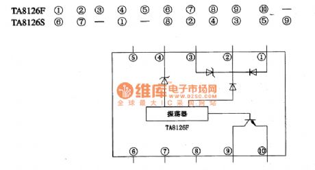
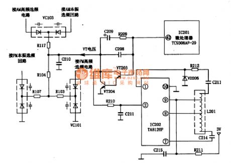
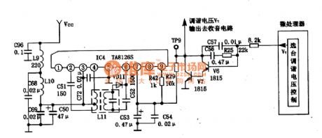
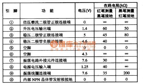
TA8126 is a DC conversion integrated circuit,and it is applied to digital tuned radio systems to provide tuned selective calling circuit with tuned voltage by promoting the DC 3V voltage to 15V around tuned voltage.TA8126 has two encapsulation methods and we can distinguish them by different suffix letters.And TA81265 adopts single inline 9 pinned package;TA8126F adopts dual inline 10 pinned package.1.inner circuit and function of pins The inner circuit of TA8126F integrated package is shown as picture 1,and the function and data of pins of its integrated circuit are shown as chart 1.
(View)
View full Circuit Diagram | Comments | Reading(894)
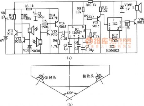
ultrasonic remote control jacklight circuit
Published:2011/6/30 1:37:00 Author:chopper | Keyword: ultrasonic, remote control, jacklight circuit
View full Circuit Diagram | Comments | Reading(485)
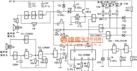
ultrasonic blind - walking device circuit
Published:2011/6/30 1:36:00 Author:chopper | Keyword: ultrasonic, blind - walking device
View full Circuit Diagram | Comments | Reading(623)
ultrasonic eyes protector cirucit
Published:2011/6/30 1:14:00 Author:chopper | Keyword: ultrasonic, eyes protector
View full Circuit Diagram | Comments | Reading(422)
VCT3803-O1A-Super TV single chip integrated circuit
Published:2011/6/17 7:44:00 Author:leo | Keyword: VCT3803-O1A-Super TV single chip integrated circuit, TDA4472, MSP3463G
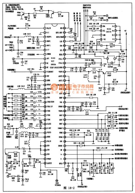
VCT3803-O1A is a kind of super TV single chip integrated circuit used in German which is widely used in big screen color television.1. Function Features:VCT3803-O1A contains micro processor, TV/AV converting circuit, brightness signal processing circuit, color signal demodulating circuit, BGR square circuit, BGR signal selecting switch circuit and so on.2.Pin Functions and data:VCT3803-O1A is used in P2960S KangJia series color television and its pin functions and data are shown in the picture. (View)
View full Circuit Diagram | Comments | Reading(892)
MCO137-Single chip micro computer control integrated circuit
Published:2011/6/17 7:42:00 Author:leo | Keyword: MCO137-Single chip micro computer control integrated circuit
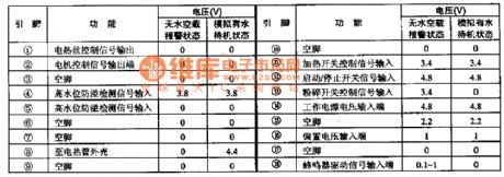
MCO137 is a kind of single chip micro computer control integrated circuit made by Motorola. It is widely used in automatically soy milk grinder.
Function Features:
MCO137 integrated circuit contains electric machinery and heating wire control circuit, key switch code control circuit, ring driving circuit, high water level detecting circuit and so on.
classic application circuit:MC1037 application is shown in the picture. (View)
View full Circuit Diagram | Comments | Reading(638)
The 50w DC transformer circuit
Published:2011/6/30 20:44:00 Author:qqtang | Keyword: DC transformer
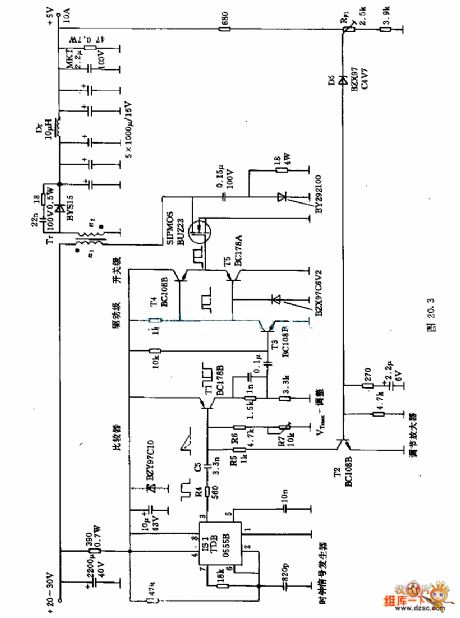
Figure:The 50w DC transformer circuit (View)
View full Circuit Diagram | Comments | Reading(483)
analyze encryption chip, encryption IC, DM2016, the copy plate chip, the copy plate IC, hardware encryption
Published:2011/6/18 23:09:00 Author:Nancy | Keyword: encryption chip, encryption IC, the copy plate chip, hardware encryption
Details:1. support I2C bus standard;2. support two bits I2C address selection;3. built-in 128 bits secret key and one-time burn;4. built-in 1024 bits E2PROM, 24C0X series IC compatible;5. SOP8 package;6. compliant with SGS
It uses a random number to produce a clear text, the special algorithm and secret key (OTP) are written unreadable one time, and buit in with 1028 Bit E2PROM. The personalized product has strong patent warranty. It has been widely used in GPS, BLUETOOTH, DV, LCD TV, DVD Car Player, DVR, Digital Photo Frame, Simulator and other embedded systems. (View)
View full Circuit Diagram | Comments | Reading(751)
Load sensor LSE application circuit
Published:2011/6/25 10:09:00 Author:Fiona | Keyword: Load sensor
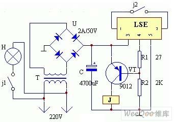
The device's electrical circuit is shown as the below picture.Plug in CT, because the normally closed contact j1 of the relay J is closed,the lamp H lights, and because the normally open contact j2 breaks,④ pin of the LSE outputs the low level,at this time the transistor VT conducts.When VT conducts,the relay J is closed, contact j1 breaks,H breaks,at the same time,the contact j2 is closed, so t④ pin of the LSE outputs the high level, transistor VT breaks,the relay J releases,the contact j1 closes again, H is lit, contact j2 breaks again ... ... so the work cycles to cycle, leading to the lamp H flashing.
(View)
View full Circuit Diagram | Comments | Reading(708)
Principle and Circuit of Single Metal and Resistance Bridge Touch Switch
Published:2011/6/28 6:05:00 Author:Michel | Keyword: Principle and Circuit, Single Metal, Touch Switch, Resistance Bridge
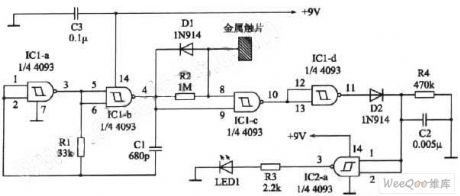
Singal Metal Touch Switch's Principle and Circuit
Work's PrincipleThe circuit shown in the picture 1 only uses a piece of sheet metal.The circuit adoptes two pieces of Schmitt triggers 4093(There are four same ends but only two of them are input ends in the circuit,such as CD4093 and TC4093.).Usually,the diode LED1 does not spark whenthe third feet of IC2-a output terminal is in low PWL.And the output terminal changes into high PWL when it touches sheet metal,which makes the LED1 glow.The figure 2 is similar to figure 1 and it uses less devices and contorl the voltage by outputing electric keys directly. (View)
View full Circuit Diagram | Comments | Reading(728)
1.5 Km Single Pipe FM Launching Circuit
Published:2011/6/22 5:04:00 Author:Michel | Keyword: 1.5 km, Single Pipe, FM, Launching Circuit
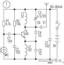
This circuit is 1.5 km single pipe FM (FM)emitting circuit.Emitting triode uses D40,D50 and 2N3866 and the work current is 60-80mA.But the aboved triode is hard to buy and the price is high and fakes are more.The author chooses other transistor to make experiments and the C2053 and C1970 is rather good.The actual horizon communication distance is over 1.5km.The author also has had changed the D40 tube into ordinary transistor 8050,its work current is 60~80mA but the emitting distance is less than 1.5m.If it is altered into 9018,the work current is much lower and the launching distance is shorter. (View)
View full Circuit Diagram | Comments | Reading(574)
Super-regenerative Wirless Receiving Circuit
Published:2011/6/22 4:56:00 Author:Michel | Keyword: Super-regenerative, Wirless, Receiving Circuit
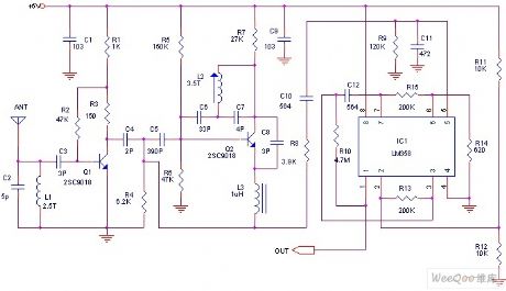
The receiver can use super regenerative circuit or tropadyne and the power consumption is 100uA.The adjustable super regenerative circuit's sensitivity is similar to first level oscillating,mixing and two-stage superheterodyne receivers.However,super regenerative circuit's work stablity and selection performance are not good which decreases anti-Impacting performance.The picture is typical tropadyne. (View)
View full Circuit Diagram | Comments | Reading(1620)
Wireless FM Emitting Circuit of 3000 Meters Launching Distance
Published:2011/6/22 4:51:00 Author:Michel | Keyword: 3000 Meters, Launching Distance, Wireless FM, Emitting Circuit
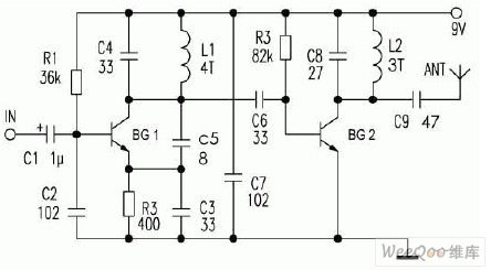

The work voltage and current are 9V and 2~6mA respectively and the element's parameters are shown as the aboved picture.BG1 is 9018,BG2 is C1959(It can be 9018 but the power is low.If the D-40 can spread the emitting distance to 1000m and it's hard to buy D-40 in shops).L1 and L2 are 0.5mm lacquered wires and the work voltage can be increased to 12V when we loope four and three circles on the 0.5 round bars.Thus the emitting distance can be increased but the frequency will change.At this time,it's better for the whole circuit uses battery charging to reach optimal results of quality and stable frequency and please turn off BG2 work and needed frequency when you start debugging and turn on BG2 circuit's adjustable power at last.
(View)
View full Circuit Diagram | Comments | Reading(585)
Low Cost Wireless Transmission Power Test Pen Circuit
Published:2011/6/22 5:44:00 Author:Michel | Keyword: Low Cost, Wireless Transmission, Power, Test Pen Circuit
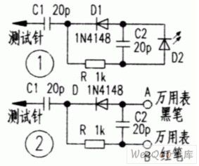
I make some testing tools according to my over 20-year wireless work experience and one effective handset interphone transmission power test pen circuit is shown as the picture.If it is installed inside the multimeter's pen, as long as we make stylus approach to interphone's antenna top.And we can judge whether the interphone has transmission power or not accurately by the LED,D2's lightness and judge emitting power magnitude roughly according to LED's lightness and darkness degree.And its production cost is no more than RMB one yuan. (View)
View full Circuit Diagram | Comments | Reading(894)
Cage Type Motor Stator Resistance Step-down Start Control Circuit
Published:2011/6/28 6:15:00 Author:Michel | Keyword: Cage Type, Motor Stator, Resistance Step-downStart Control Circuit
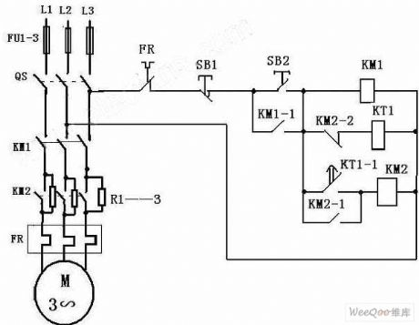
Cage Type Motor Stator Resistance Step-down Start Control Circuit (View)
View full Circuit Diagram | Comments | Reading(1576)
Isolated Industry Control Voltage Output Circuit of AD5562
Published:2011/6/22 6:10:00 Author:Michel | Keyword: Isolated Industry , Control Voltage, Output Circuit
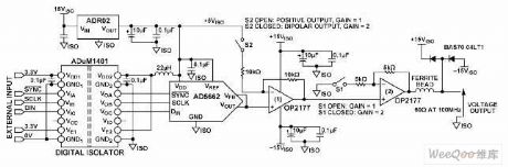
This circuit's industrial control output module provides a complete solution scheme.This design is applied to PLCs which needs dual output voltage and DCSes.AD5662 is a 16-bit 5 V power supply and SOT-23 encapsulation digital-to-analog converter.ADuM1401 four channel digital isolatior provides all signal isolation between micro controller and digital-to-analog converter.The circuit is complete with the external protection standard of IEC 61000 specifications by test and verification. (View)
View full Circuit Diagram | Comments | Reading(530)
| Pages:389/471 At 20381382383384385386387388389390391392393394395396397398399400Under 20 |
Circuit Categories
power supply circuit
Amplifier Circuit
Basic Circuit
LED and Light Circuit
Sensor Circuit
Signal Processing
Electrical Equipment Circuit
Control Circuit
Remote Control Circuit
A/D-D/A Converter Circuit
Audio Circuit
Measuring and Test Circuit
Communication Circuit
Computer-Related Circuit
555 Circuit
Automotive Circuit
Repairing Circuit