
Index 442
74 series digital circuit of 74H87 binary true form/inverse code and O/I circuit
Published:2011/4/2 4:09:00 Author:Ecco | Keyword: digital circuit , binary true form, Anti-code , O/I circuit
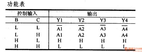
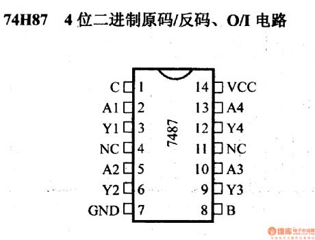
74H87 binary true form/Anti-code, O/I circuit (View)
View full Circuit Diagram | Comments | Reading(819)
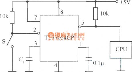
Voltage monitoring and reset circuit with TL7705CP
Published:2011/4/20 4:38:00 Author:Nicole | Keyword: Voltage monitoring, reset
View full Circuit Diagram | Comments | Reading(626)
TIL probe circuit
Published:2011/4/20 8:55:00 Author:Nicole | Keyword: probe
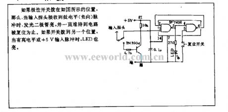
If the polarity switch is in the position as shown, when the input probe receives low level(nagative)pulse, LED lights and it will keep lighting until the circuit is reset. If the switch is put to another position, when there is high level or +5V input pulse, LED lights too. (View)
View full Circuit Diagram | Comments | Reading(627)
74 series digital circuit of 74107 74LSO7A double J - K edge trigger
Published:2011/4/2 3:56:00 Author:Ecco | Keyword: digital circuit, double J - K negative edge, trigger
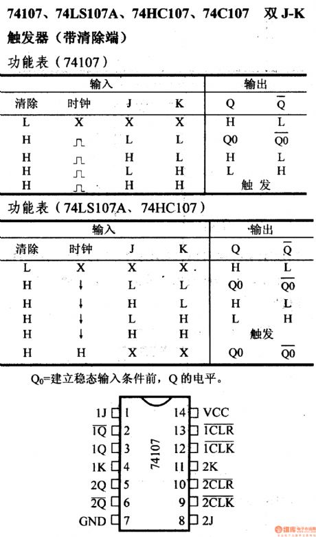
74 series digital circuit of 74107 74LSO7A double J - K negative edge trigger( with remove terminal)
(View)
View full Circuit Diagram | Comments | Reading(1675)
74 series digital circuit of 74LS113 74S113 double J - K negative edge trigger
Published:2011/3/31 21:18:00 Author:Ecco | Keyword: digital circuit , double J - K , negative edge trigger
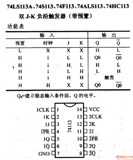
74 series digital circuit of 74LS113,74S113 double J - K negative edge trigger (with preset)
(View)
View full Circuit Diagram | Comments | Reading(1360)
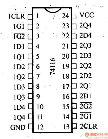
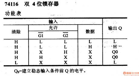
74 series digital circuit of 74116 dual 4-bit latch
Published:2011/4/2 3:55:00 Author:Ecco | Keyword: digital circuit , dual 4-bit latch
View full Circuit Diagram | Comments | Reading(999)
74 series digital circuit of 74120 pulse synchronizer/driver
Published:2011/4/2 3:55:00 Author:Ecco | Keyword: digital circuit, pulse synchronizer, pulse driver
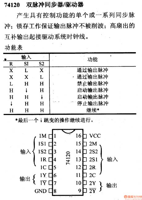
74120 double pulse synchronizer/driver
It producesa single or a series of synchronous pulse with controlling function; Latch job promises that the output pulse won't be cut wave. High fan-outoutput complementary connects clock line drive system.
(View)
View full Circuit Diagram | Comments | Reading(852)
Power output stage diagram circuit of switching power supply
Published:2011/4/20 1:21:00 Author:May | Keyword: Power output stage, switching power supply

Power output stage diagram circuit of switching power supply (50KHz-120KHz 1KW-2KW) (View)
View full Circuit Diagram | Comments | Reading(2222)
Push pull circuit using complementary transistor and CMOS driving stage
Published:2011/4/19 22:38:00 Author:May | Keyword: Push pull, complementary transistor, CMOS driving stage
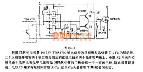
It is using CMOS inverter 4049 as driving stage of inverter stage of TDA4700 's output signal and transistor T1, T2. Three inverters are parallel. Two output ends among them are separately adding to the base of two transistors in push pull circuit. Resistor R2 is used for controlling the circuit. When it can not guarantee enough voltage for SIPMOS tube's gate pole to offer a fixed potential, it can prevent the error breaking over of this tube. Capacitor C3 is used for shorting time constant R2CBE. Here, CBE is capacitor between base-emitter of transistor T. (View)
View full Circuit Diagram | Comments | Reading(1126)
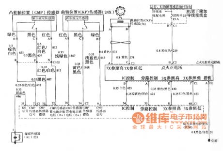
Buick GL8 camshaft position CMP sensor, crankshaft position CKP sensor, ignition electronic control unit ICM circuit
Published:2011/4/20 2:47:00 Author:Jessie | Keyword: camshaft position CMP sensor, crankshaft position CKP sensor, ignition electronic control unit ICM
View full Circuit Diagram | Comments | Reading(665)
Drive circuit diagram based on a bridge type motor
Published:2011/4/2 4:24:00 Author:may | Keyword: drive, bridge type motor
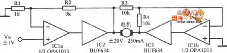
Based on a kind of Mazda driver circuit is show in the following picture:
(View)
View full Circuit Diagram | Comments | Reading(447)
24Mb data line
Published:2011/4/11 1:09:00 Author:muriel | Keyword: 24Mb , data line
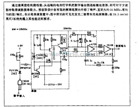
Through improving the performance of the receiver, the distant teletypewriter send the digital output to microprocessor, they can be obtained high data rate ability from square wave pulsed. The design of preamplifier compensates noise in a limited frequency range, until about 20MHz, with uniform signal / noise ratio. In the demonstration device, as shown in the figure visible light-emitting diodes and photodetectors, on the cable which is 19.2cm (40 feet) long its performance can meet the requirements. (View)
View full Circuit Diagram | Comments | Reading(562)
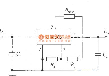
The standard application circuit of 5 end adjustable output voltage integrated regulator CW200
Published:2011/4/19 1:34:00 Author:muriel | Keyword: standard application circuit , 5 end, adjustable , output voltage, integrated , regulator
View full Circuit Diagram | Comments | Reading(486)
10Mb optical data circuit
Published:2011/4/18 2:33:00 Author:muriel | Keyword: 10Mb, optical data circuit
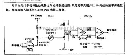
The optical data circuit is used for between teletypewriter and micro place view device, it uses the broadband fiber optic to transmit dataat the rate of 10Mb. Receiver input end use C3808 PIN photosensitive diode.
(View)
View full Circuit Diagram | Comments | Reading(614)
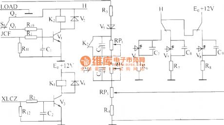
DZW75-48/5050II equalized charge and floating charge change over circuit
Published:2011/4/14 1:21:00 Author:muriel | Keyword: equalized charge, floating charge, change over circuit
View full Circuit Diagram | Comments | Reading(546)
Adjustable constant temperature controller circuit diagram
Published:2011/4/19 4:36:00 Author:Nicole | Keyword: constant temperature controller
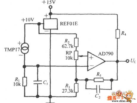
The adjustable constant temperature controller circuit is asbelow. REF01E provides TMP17 with 10V high steady power supply, it can obtain a voltage singal from resistor R1, the voltage is in direct proportion t0 the measured temperature t. AD790 is a voltage comparator. If t represents the measured temperature and to represents the set value, when t>t0, the output of constant temperature controller is low level, when t<t0, it is high level. The value of to can be adjusted by potentiometer PR. C1 is denoising capacitance, C2 is accelerate capacitance. The output terminal of temperature control circuit controls the electric heating device by means of all kinds of actuators, then to achieve temperature control.
(View)
View full Circuit Diagram | Comments | Reading(848)
900w full wave circuit
Published:2011/4/14 2:20:00 Author:muriel | Keyword: 900w, full wave circuit
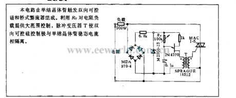
The circuit is composed ofSingle junction transistor trigger bidirectional triode thyristor and bridge rectifier. It use theRT control a wide range of resistive load . Pulse transformer T isolates the single junction transistor steady-state current and silicon-controlled rectifier control extremely.
(View)
View full Circuit Diagram | Comments | Reading(993)
Constant current source circuit with CW7900
Published:2011/3/30 2:08:00 Author:muriel | Keyword: constant current source circuit

View full Circuit Diagram | Comments | Reading(468)
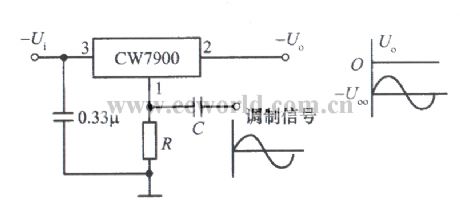
Power amplitude modulator circuit with CW7900
Published:2011/3/30 2:07:00 Author:muriel | Keyword: power amplitude modulator
View full Circuit Diagram | Comments | Reading(569)
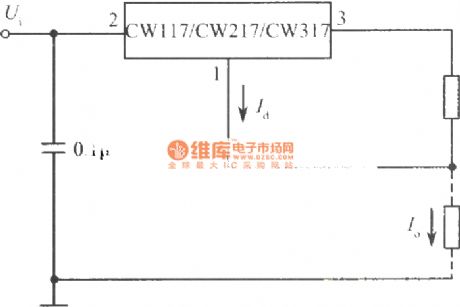
Standard constant current source circuit with CW117
Published:2011/3/30 2:07:00 Author:muriel | Keyword: standard , constant current source circuit
View full Circuit Diagram | Comments | Reading(497)
| Pages:442/471 At 20441442443444445446447448449450451452453454455456457458459460Under 20 |
Circuit Categories
power supply circuit
Amplifier Circuit
Basic Circuit
LED and Light Circuit
Sensor Circuit
Signal Processing
Electrical Equipment Circuit
Control Circuit
Remote Control Circuit
A/D-D/A Converter Circuit
Audio Circuit
Measuring and Test Circuit
Communication Circuit
Computer-Related Circuit
555 Circuit
Automotive Circuit
Repairing Circuit