
Index 100
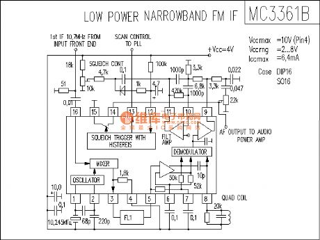
MC3361B circuit
Published:2011/11/11 2:10:00 Author:Ecco
View full Circuit Diagram | Comments | Reading(1142)
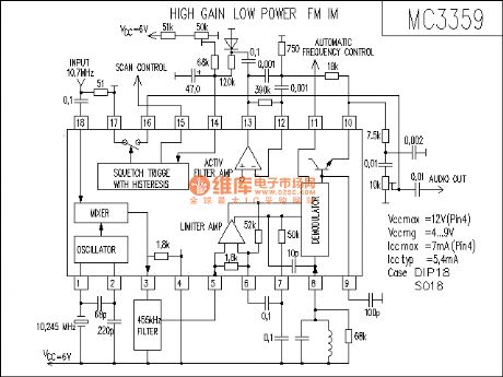
MC3359 receiver circuit
Published:2011/11/11 2:10:00 Author:Ecco | Keyword: receiver circuit
View full Circuit Diagram | Comments | Reading(2347)
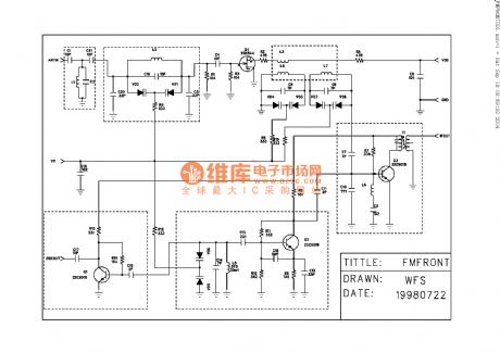
Classic tuner circuit
Published:2011/11/11 2:19:00 Author:Ecco | Keyword: Classic tuner
View full Circuit Diagram | Comments | Reading(913)
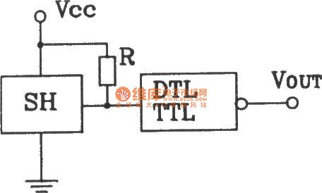
The connection output interface circuit between SH Hall switch and DTL, TTL
Published:2011/11/1 21:49:00 Author:Ecco | Keyword: connection , output interface, Hall switch, DTL, TTL
View full Circuit Diagram | Comments | Reading(703)
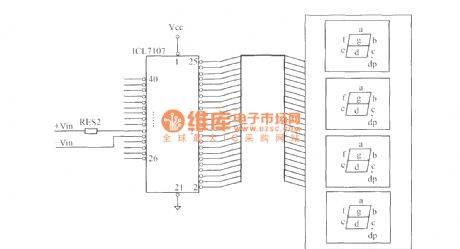
Dynamic scan display circuit
Published:2011/11/10 3:32:00 Author:Ecco | Keyword: Dynamic scan display
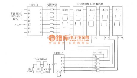
The circuit shown as the chart is thedynamic scan display circuitcomposed ofdecoder driver CD4511, beat generator CD4017, 7 roads ofDarlington drivers MC1413. LED1 ~ LED5 are five common cathode LED displays .
(View)
View full Circuit Diagram | Comments | Reading(1956)
Relay status indication circuit
Published:2011/11/10 3:02:00 Author:Ecco | Keyword: Relay status indication
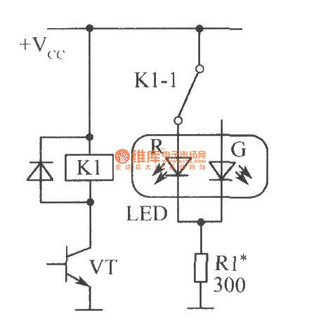
The relay has one or more sets of contacts, if one set of contacts'common port connect to the public power, and in the release state, the common port is connected to the normally closed contacts, then LED-R is red ; and in the pull-in state, the common port is connected to the normally open contact, then LED-G is green.
(View)
View full Circuit Diagram | Comments | Reading(861)
Digital hygrometer
Published:2011/11/7 19:12:00 Author:Ecco | Keyword: Digital hygrometer
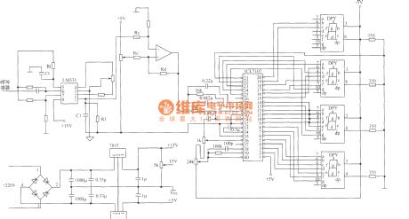
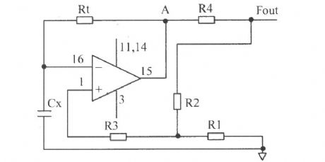
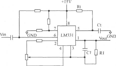
Digital hygrometer mainly consists of the following circuits :(1 ) humidity / voltage conversion circuit; (2 ) humidity / frequency converter circuit; (3 )the circuit composed of LM331.
(View)
View full Circuit Diagram | Comments | Reading(2294)
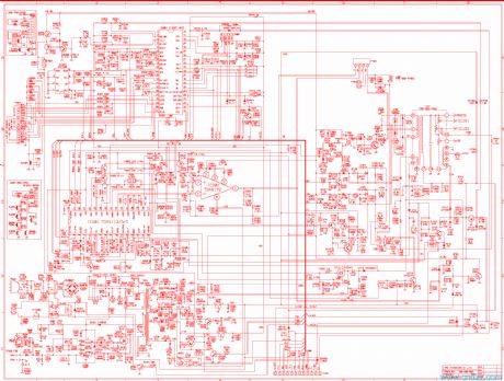
770FS monitor blueprint
Published:2011/11/3 2:25:00 Author:Ecco | Keyword: monitor blueprint
View full Circuit Diagram | Comments | Reading(1669)
4-tube transmitter schematic diagram
Published:2011/11/11 2:19:00 Author:Ecco | Keyword: 4-tube transmitter
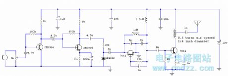
Circuit Notes This circuit provides an FM modulated signal with an output power of around 500mW. The input Mic preamp is built around a couple of 2N3904 transistors, audio gain limited by the 5k preset. The oscillator is a colpitts stage, frequency of oscillation governed by the tank circuit made from two 5pF capacitors and the inductor. ( Click here for Colpitt Oscillator Resonant Frequency Equation.) Frequency is around 100Mhz with values shown.
Audio modulation is fed into the tank circuit via the 5p capacitor, the 10k resistor and 1N4002 controlling the amount of modulation. The oscillator output is fed into the 3.9uH inductor which will have a high impedance at RF frequencies.
The output stage operates as a class D amplifier , no direct bias is applied but the RF signal developed across the 3.9uH inductor is sufficient to drive this stage. The emitter resistor and 1k base resistor prevent instability and thermal runaway in this stage.
(View)
View full Circuit Diagram | Comments | Reading(2073)
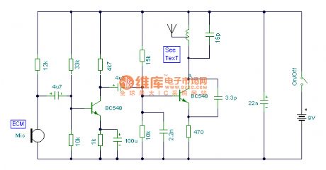
The simple FM emitter circuit
Published:2011/11/11 2:25:00 Author:Ecco | Keyword: simple FM emitter
View full Circuit Diagram | Comments | Reading(741)
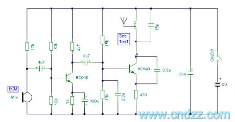
Simple FM emitter circuit diagram
Published:2011/11/11 2:24:00 Author:Ecco | Keyword: Simple FM emitter
View full Circuit Diagram | Comments | Reading(738)
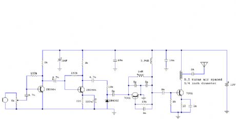
4-tube FM Transmitter
Published:2011/11/11 2:18:00 Author:Ecco | Keyword: 4-tube FM Transmitter
View full Circuit Diagram | Comments | Reading(1157)
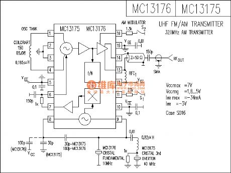
MC13175-76 FM receiver circuit
Published:2011/11/11 2:11:00 Author:Ecco | Keyword: FM receiver
View full Circuit Diagram | Comments | Reading(975)
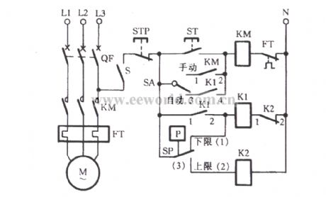
The automatic controlling circuit of electric contact pressure gauge connecting intermediate relay
Published:2011/11/8 21:18:00 Author:Ecco | Keyword: automatic controlling , electric contact , pressure gauge, connecting, intermediate relay
View full Circuit Diagram | Comments | Reading(1363)
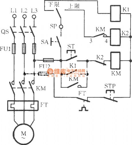
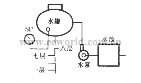
Electric pressure gauge connecting controlling water pump circuit 1
Published:2011/11/8 21:16:00 Author:Ecco | Keyword: Electric pressure gauge, connecting, controlling water pump
View full Circuit Diagram | Comments | Reading(2570)
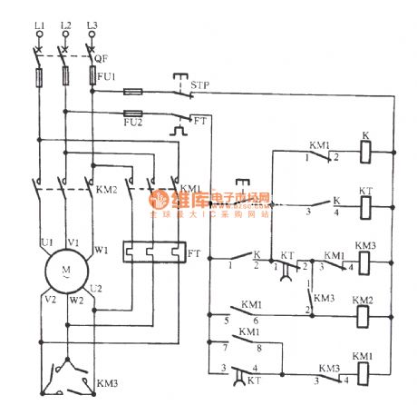
The Y-△ starting circuit 1 for motor without power switch
Published:2011/11/3 2:04:00 Author:Ecco | Keyword: Y-△ starting , motor , without power switch
View full Circuit Diagram | Comments | Reading(700)
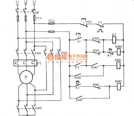
The Y-△ starting circuit 2 for motor without power switch
Published:2011/11/3 2:05:00 Author:Ecco | Keyword: Y-△ starting , motor , without power switch
View full Circuit Diagram | Comments | Reading(728)
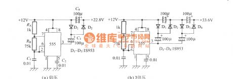
The boost circuit using Timer IC
Published:2011/11/7 21:41:00 Author:Ecco | Keyword: boost circuit , Timer IC
View full Circuit Diagram | Comments | Reading(824)
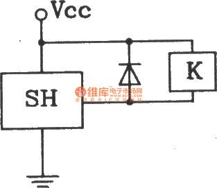
The output interface circuit between SH Hall switch and driver relay
Published:2011/11/1 21:55:00 Author:Ecco | Keyword: output interface, Hall switch, driver relay
View full Circuit Diagram | Comments | Reading(627)
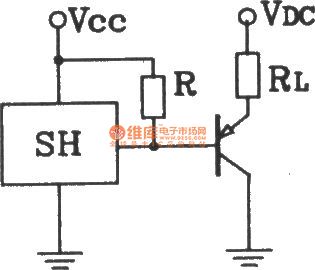
The output interface circuit between SH Hall switch and collector
Published:2011/11/1 22:00:00 Author:Ecco | Keyword: output interface , Hall switch, collector
View full Circuit Diagram | Comments | Reading(570)
| Pages:100/471 At 2081828384858687888990919293949596979899100Under 20 |
Circuit Categories
power supply circuit
Amplifier Circuit
Basic Circuit
LED and Light Circuit
Sensor Circuit
Signal Processing
Electrical Equipment Circuit
Control Circuit
Remote Control Circuit
A/D-D/A Converter Circuit
Audio Circuit
Measuring and Test Circuit
Communication Circuit
Computer-Related Circuit
555 Circuit
Automotive Circuit
Repairing Circuit