
Basic Circuit
Index 26
Toy Throttle-Zero Indication
Published:2013/6/25 22:03:00 Author:muriel | Keyword: Toy Throttle, Zero Indication
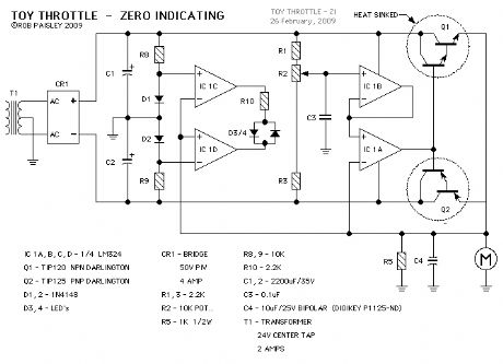
With this type of throttle would be difficult to know when the output is at ZERO . To help with this a ZERO indicator has been added to the next drawing. The indicator can also show the trains direction.The above schematic shows the addition of a Zero Indicating circuit to the throttle. When the output voltage is between +0.7 and -0.7 Volts both of the LED's, D3/4 will be OFF. As the output voltage increases, either PLUS or MINUS, one of the LED's will turn ON.
This will allow the operator to know when the throttle's output voltage is near ZERO and the train is safely stopped.
As there are two LED's, they can also show the direction of travel based on the polarity of the output voltage.
A two colour LED could be used for D3/4. This will give a GREEN indication for one direction and a RED indication for the other.
The next schematic shows an optional ZERO indication method. In this case the LED will be ON when the throttles output is near ZERO. (View)
View full Circuit Diagram | Comments | Reading(866)
Toy Throttle - Push Button Control
Published:2013/6/25 22:02:00 Author:muriel | Keyword: Toy Throttle , Push Button Control
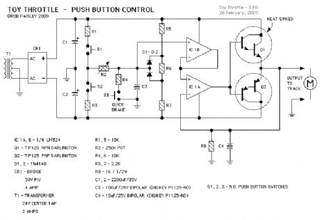
This next circuit is a variation on the Basic Toy throttle. In this version three push buttons are used to control the output.
Button S1 causes the train to move in one direction while S2 moves it in the other. Button S3 is the Quick or emergency brake that will stop the train very quickly.
An interesting feature of this system is that the train could be brought to a stop and then move off in the opposite direction by pressing only one button. Useful for shunting perhaps.
Resistors R5, R6, R7 and diodes D1, D2 form a voltage limiter that reduces the maximum output voltage swing as mentioned in the potentiometer controlled circuit description. (View)
View full Circuit Diagram | Comments | Reading(963)
Modernized "Toy" Throttle
Published:2013/6/25 22:02:00 Author:muriel | Keyword: Modernized "Toy" Throttle

This throttle is an upgrade of the type of throttle that is supplied with many of the HO train sets that are popular at Christmas time. These throttles do not have a reversing switch but instead have a center OFF position on the speed control knob.
While this throttle may seam like a step backward in the evolution of train controls it does have features that make it useful in certain situations.
Due to its one control operation it would be ideal for small children and persons with reduced hand dexterity.
There is no chance of the direction suddenly being reversed while the train is under way as the output control would have to pass through ZERO in order to change direction.
It would also be possible to have a spring loaded, one axis joystick type control that would automatically stop the train when the lever is released and as there is only one control it could be as large as desired. Again this might be helpful for someone who could not easily manipulate small controls or small children who would have an easier time with just one control.The above schematic shows the basic Toy Throttle. It is powered by a 24 Volts AC, Center Tapped transformer to provide PLUS and MINUS voltages.
The throttle uses a Push-Pull amplifier that eliminates the need for a reversing relay or switch.
When resistor R2 is in the CENTER position the throttles output voltage would be ZERO . Adjusting R2 up or down would produce positive or negative voltage to the track thereby controlling the trains direction.
Resistors R1 and R3 limit the maximum output voltage to between PLUS or MINUS 10 Volts. (View)
View full Circuit Diagram | Comments | Reading(724)
Regulated Current Pulse Throttle
Published:2013/6/25 22:01:00 Author:muriel | Keyword: Regulated Current , Pulse Throttle
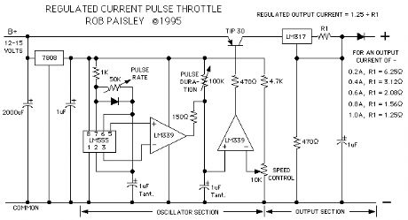
The next throttle is more than a little different, it's very different but in its own unique way it works just fine. It is however posted here for interest sake only and should not be viewed as a major discovery or some sort of magic trick.
The design uses the variable pulse width oscillator that is the at the heart of the Variable Pulse Type Throttle as shown above. The oscillator in this circuit however switches a current regulator constructed from an LM317 voltage regulator.
Rather than regulating the output voltage this throttle instead produces variable width pulses of a fixed current value, for example 200 or 400mA. The voltage can rise to a level that is determined largely by the B+ input voltage and the drop across the LM317 but the motor can only receive the maximum current that the LM317 will pass. This current value is determined by the value of R1. (View)
View full Circuit Diagram | Comments | Reading(869)
Pulse Type Throttle Schematic
Published:2013/6/25 22:00:00 Author:muriel | Keyword: Pulse Type , Throttle Schematic
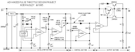
The next schematic is for an advanced type of pulse throttle. Simply put, as the output voltage is increased by the 10K pot, a pulse is injected onto the the control voltage at the PLUS input terminal of the second LM358 OpAmp. As the control voltage increases the width of the pulse is also increased.The height of the pulse is adjusted so that at some point it is overtaken by the output of the first OpAmp section. From this point on the output from the throttle is pure DC
The duration of the pulse is adjusted so that it is at approximately 50% when the pulse voltage is overtaken by the output control voltage.
The pulse rate can also be varied but whenever the rate is adjusted the other variables of the oscillator will be thrown off and all would have to be reset.
To properly set up this particular throttle an oscilloscope is required.
Overall this particular throttle did not perform as I had hoped it might, but seemed to work well for locomotives with good quality motors. (View)
View full Circuit Diagram | Comments | Reading(757)
A Full and Half-Wave DC Test Throttle
Published:2013/6/25 21:59:00 Author:muriel | Keyword: Full, Half-Wave, DC Test Throttle
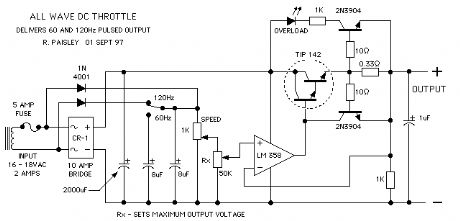
The next throttle is one that was put together for testing purposes only. As can be seen it is a modification of the basic transistor throttle shown above. The SPDT switch allows the throttle to have a full or half wave DC output.
The value of the 8 uF capacitors is calculated to allow the voltage across the 1000 ohm potentiometer to decay to 1/3 of the supply voltage before the next cycle starts. At 120 Hz; 8 uF is needed and at 60 Hz; 16 uF is required to achieve this result.
This means that the peak output voltage of the throttle has value that is three times the lowest voltage of the output for a given throttle setting. Please refer to the wave forms diagram below the schematic for clarification.If the 8 uF capacitors are omitted, the circuit becomes an overly-complicated, fullwave DC throttle.
The throttle as shown has an automatic current limiting of about 2 amps and a quasi-regulated output voltage.
This throttle gave pretty good results with an Atlas locomotive and one from a starter set of the type that make their appearance at Christmas time. (View)
View full Circuit Diagram | Comments | Reading(988)
Basic Throttle with Unplugable Walk Around Control
Published:2013/6/25 21:59:00 Author:muriel | Keyword: Basic Throttle, Unplugable Walk Around Control
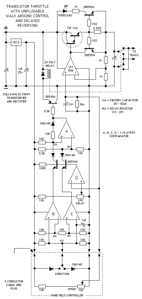
next up is the basic transistor throttle with unplugable walk around control added. The direction memory uses an LM339 quad comparator and has a delayed action so that the direction can not change if the throttle output is above a predetermined voltage.
The delayed reverse section, comparator section D, of the circuit grounds the bases of the transistors whenever the voltage at its PLUS input is higher than the reference voltage at the MINUS input. The PLUS input is connected to the throttle control voltage line.
When the transistor bases are grounded they cannot conduct and any changes at their emitters will have no effect until the control voltage again falls below the preset level.
Comparator sections B and C function as a voltage window detector. That is to say the outputs of both section Band C are high as long as the direction signal voltage is between 4 and 8 volts. If the signal goes below 4 volts or above 8 volts the appropriate output will go low and the direction will change accordingly.
If the controller is unplugged the direction signal will go to 6 volts and the train will maintain its last direction.
Please refer to the voltage comparator information page on this web site for help on how comparators work. (View)
View full Circuit Diagram | Comments | Reading(692)
Walkaround Throttle With Auxiliary Controls Schematic
Published:2013/6/25 21:57:00 Author:muriel | Keyword: Walkaround Throttle, Auxiliary Controls Schematic

A variation on the walkaround throttle is in the next circuit. If extra wires are added to the control cable they can be put to use for operating accessories on the layout.
For every extra wire 2 such loads can be controlled. Electromagnetic uncoupling ramps could be turned on and off, train whistles could be blown or a reverse loop switch can be thrown after the train has passed.By using 4N33 Darlington output Optoisolators as low power relays and adding two push buttons or a toggle switch to the hand held controller a wide variety of external devices could be operated with only a small current draw on the throttle circuit itself.
Unplugable operation would still be a feasible option even with six wires in the control cable. This would allow four auxiliary control outputs.
The optoisolator by itself can only handle a load current of 20 milliamps, larger load currents require adding another transistor. The next drawing is shows a more detailed view of the auxiliary outputs. (View)
View full Circuit Diagram | Comments | Reading(921)
Walkaround Transistor Throttle Schematic
Published:2013/6/25 21:57:00 Author:muriel | Keyword: Walkaround Transistor , Throttle Schematic
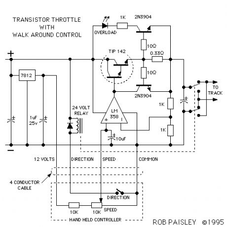
In the next circuit walk around control is added to the throttle. A 4 conductor, 22 Gauge stranded cable will allow the operator to move around with the 'Hand Held Controller' while the power section of the throttle remains at a fixed location.
A DPDT 24 Volt DC relay and a toggle switch has been added for direction control. The direction switch, speed control potentiometer and a 10K ohm resistor are mounted in the Hand Held Controller. (View)
View full Circuit Diagram | Comments | Reading(1191)
Basic Transistor Throttle Schematic
Published:2013/6/25 21:56:00 Author:muriel | Keyword: Basic Transistor, Throttle Schematic
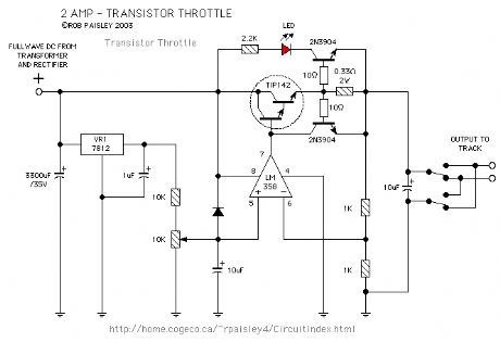
The first circuit is a 2 Amp, 0-12 Volt, voltage regulator type circuit. It uses a 10K ohm potentiometer to control the output voltage and has a light emitting diode that will indicate an overload condition. A DPDT toggle switch controls the train direction. The TIP142 output transistor will need a heat sink to keep it cool and the 0.33 ohm resistor should have a 5 Watt power rating. The OPAMP is one half of an LM 358. One quarter of a LM 324 could also be used. (View)
View full Circuit Diagram | Comments | Reading(1436)
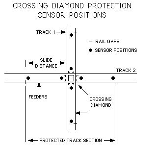
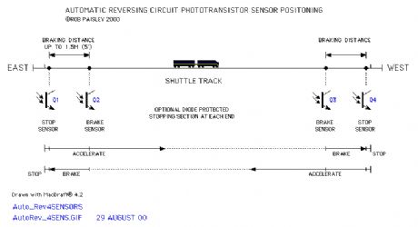
Phototransistor Sensor Placement
Published:2013/6/25 21:46:00 Author:muriel | Keyword: Phototransistor Sensor Placement
View full Circuit Diagram | Comments | Reading(697)
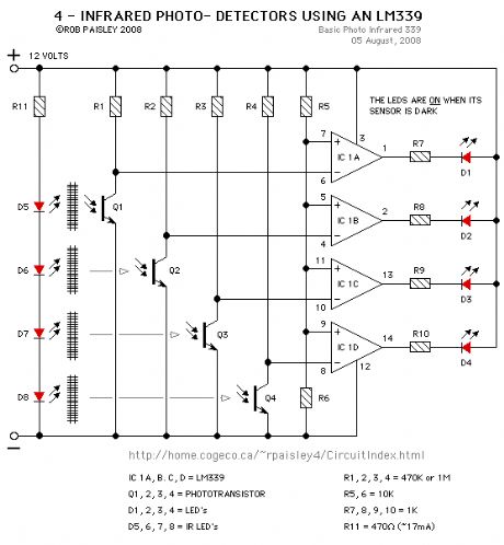
4 - Infrared Detectors
Published:2013/6/25 21:40:00 Author:muriel | Keyword: 4 - Infrared Detectors
View full Circuit Diagram | Comments | Reading(621)
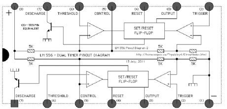
Pinout Diagrams 3
Published:2013/6/25 21:38:00 Author:muriel | Keyword: Pinout Diagrams
View full Circuit Diagram | Comments | Reading(819)
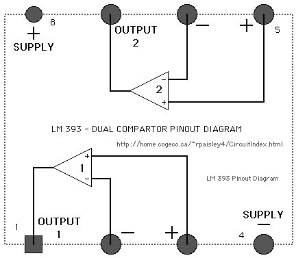
Pinout Diagrams 2
Published:2013/6/25 21:38:00 Author:muriel | Keyword: Pinout Diagrams
View full Circuit Diagram | Comments | Reading(803)
Pinout Diagrams
Published:2013/6/25 21:37:00 Author:muriel | Keyword: Pinout Diagrams

View full Circuit Diagram | Comments | Reading(944)
Using Multiple Phototransistors
Published:2013/6/24 21:46:00 Author:muriel | Keyword: Using Multiple Phototransistors
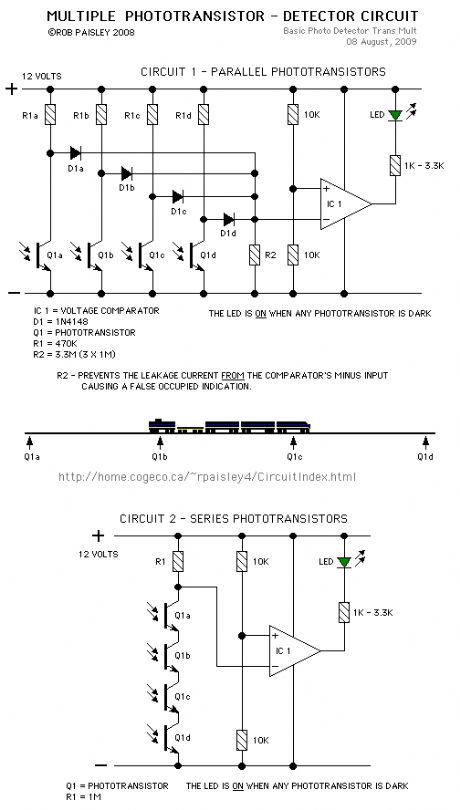
More than one phototransitor can be connected to a single voltage comparator. This would allow transistors to be placed along a section of track to indicate when a train is anywhere in that section.
As long as the train is long enough to cover two sensors the circuit will continuously detect the train.
(View)
View full Circuit Diagram | Comments | Reading(1002)
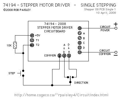
Single-Step Input
Published:2013/6/21 3:13:00 Author:muriel | Keyword: Single-Step Input
View full Circuit Diagram | Comments | Reading(881)
Basic Diode Matrix System
Published:2013/6/21 3:06:00 Author:muriel | Keyword: Basic Diode Matrix System
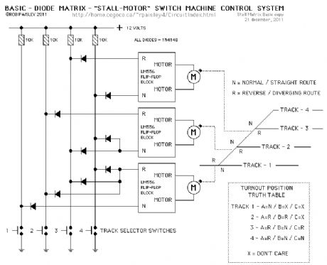
The next diagram is for a basic diode matrix system that will operate the switch machines for one end of a four track ladder yard.
Tracks 1 through 4 are selected with the appropriate push buttons. This in turn SET's or RESET's, through the diode matrix, the appropriate switch machine motor controller to its N or R condition and operates the turnouts.Included in the diagram is a Truth Table that shows the position of each turnout for the particular track that is selected. The X or DON'T CARE symbol means that it does not matter where that turnout is lined to if track 1 or 2 is selected. (View)
View full Circuit Diagram | Comments | Reading(1263)
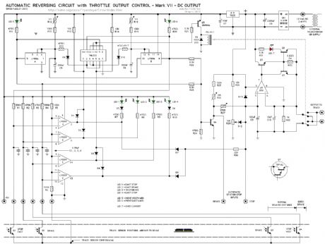
Automatic Reversing Circuit Schematic - DC Output
Published:2013/6/21 3:04:00 Author:muriel | Keyword: Automatic Reversing Circuit, DC Output
View full Circuit Diagram | Comments | Reading(814)
phototransistor sensors
Published:2013/6/21 3:04:00 Author:muriel | Keyword: phototransistor sensors
View full Circuit Diagram | Comments | Reading(683)
| Pages:26/471 At 202122232425262728293031323334353637383940Under 20 |
Circuit Categories
power supply circuit
Amplifier Circuit
Basic Circuit
LED and Light Circuit
Sensor Circuit
Signal Processing
Electrical Equipment Circuit
Control Circuit
Remote Control Circuit
A/D-D/A Converter Circuit
Audio Circuit
Measuring and Test Circuit
Communication Circuit
Computer-Related Circuit
555 Circuit
Automotive Circuit
Repairing Circuit