
Basic Circuit
Index 30
2 Sets Of 2 Inputs To 4 Discrete Outputs
Published:2013/6/13 1:25:00 Author:muriel | Keyword: 2 Sets, 2 Inputs To 4 , Discrete Outputs
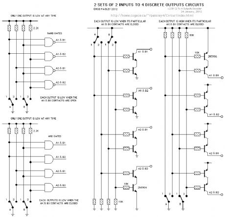
These circuits are to designed to convert the inputs from 2 SPST swiches and convert it to 4 discrete outputs. Depending on the particular circuit used, only one output can be HIGH or LOW at a time.
The NAND and AND logic gates can operate in either the HIGH or LOW output mode as their outputs are bipolar. The output of the logic devices could also be the open collector type.
The number of SPST inputs and discrete outputs can be increased by using additional logic gates with an input for each set of contacts. (View)
View full Circuit Diagram | Comments | Reading(918)
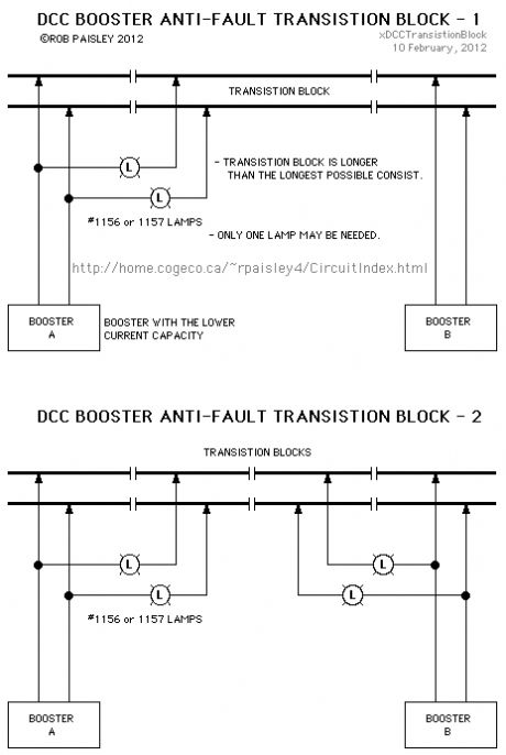
DCC Booster Anti-Fault Transistion Block
Published:2013/6/13 1:23:00 Author:muriel | Keyword: DCC Booster, Anti-Fault Transistion Block
View full Circuit Diagram | Comments | Reading(803)
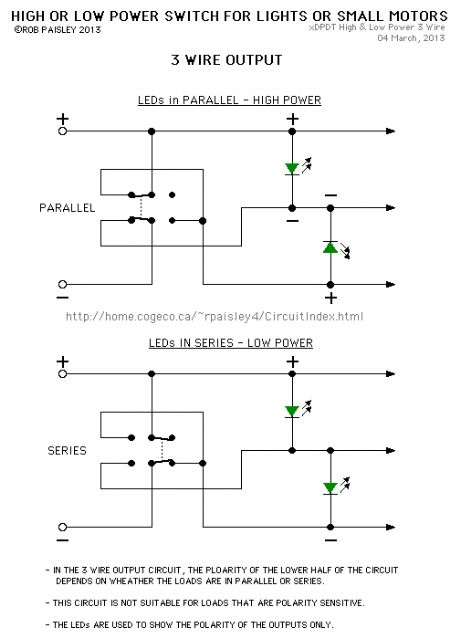
3 Wire Output Circuit
Published:2013/6/7 21:41:00 Author:muriel | Keyword: 3 Wire , Output Circuit
View full Circuit Diagram | Comments | Reading(752)
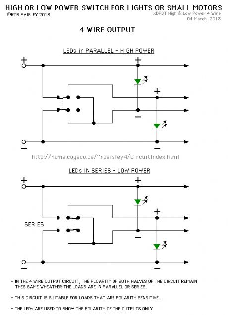
4 Wire Output Circuit
Published:2013/6/7 21:40:00 Author:muriel | Keyword: 4 Wire, Output Circuit
View full Circuit Diagram | Comments | Reading(651)
Finding The Coil Resistance Of A Meter
Published:2013/6/7 21:40:00 Author:muriel | Keyword: The Coil Resistance , Meter
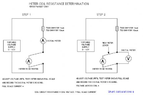
The following diagram shows a method for finding the coil resistance of a meter. Sometimes the coil resistance is marked on the meter face below the clear area of the meter's window. (View)
View full Circuit Diagram | Comments | Reading(727)
Volts and Amps Schematic
Published:2013/6/7 21:39:00 Author:muriel | Keyword: Volts and Amps Schematic
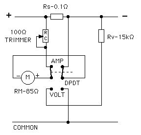
A D.P.D.T. switch and the original voltmeter calibrating resistor (Rv) could be added to the circuit allowing one meter to be used for both amps and volts. See the schematic below. (View)
View full Circuit Diagram | Comments | Reading(686)
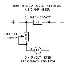
1.5 AMP - Shunt Ammeter Circuit
Published:2013/6/7 21:39:00 Author:muriel | Keyword: 1.5 AMP, Shunt Ammeter Circuit
View full Circuit Diagram | Comments | Reading(678)
5 Times Around Circuit
Published:2013/6/7 21:36:00 Author:muriel | Keyword: 5 Times Around Circuit
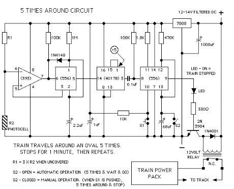
The 5 Times Around circuit was designed to automatically let an N Scale locomotive and car travel around a loop 5 times and stop for approximately a minute and then repeat the cycle. The loop of track was set up as an amusement park type of ride in the trolley section of The London Model Railroad Group's, 'O' scale layout. The club is located at London, Ontario, Canada. (View)
View full Circuit Diagram | Comments | Reading(901)
Basic Solid State Relays
Published:2013/6/7 21:35:00 Author:muriel | Keyword: Basic Solid State Relays
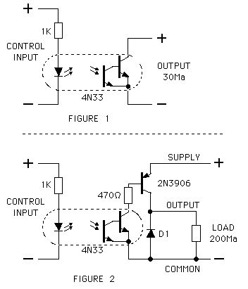
The following are examples of home made solid state relays that could be used to replace mechanical types in many model railroad circuits.
These Relays would be ideal for applications where many relays are needed and the load current requirements are low. Due to their small size a large number of relays could be mounted on a single printed circuit board.
The relays are based on a 4N33 Optoisolator package. This device has a Darlington output transistor and as the first figure shows it can be used alone for low power applications of up to 30Ma. The second figure shows a version for higher current loads of up to 250Ma. (View)
View full Circuit Diagram | Comments | Reading(1375)
The "MoAT" Project Throttle.
Published:2013/6/7 21:34:00 Author:muriel | Keyword: The "MoAT" Project Throttle.
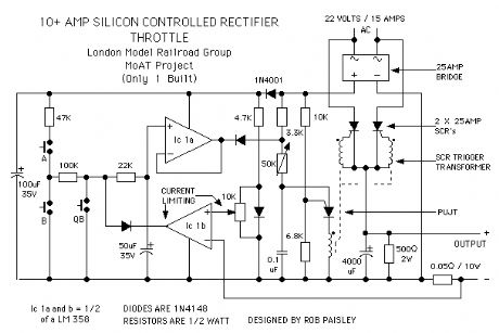
The third schematic is a throttle that was built for the London Model Railroad Group because of a quest for more power (amps) to triple head an all brass 21 hopper coal drag with scratch built Steam locomotives.
A quest ranking somewhere between that for the Holy Grail and the Golden Fleece. The fact that the transformer (22 Volts and 15 Amps) that powers this throttle just happened to appear at the right time helped get it off the ground.
As the schematic shows this design uses two silicon controlled rectifiers that are triggered through a special SCR trigger transformer. This transformer allows the cathodes and gates of the SCR's to be isolated from the control circuit and thus permitting the incorporation of the over current protection into the throttle.
The SCR's form half of a rectifier bridge that provides the track power while the two diodes in the bridge module that the SCR's replace supply power only to the PUJT and the control circuits. In effect the power flow through each SCR's is halved because each is triggered on every other cycle of the full wave DC.
The current limiting simply bleeds the charge off of the memory capacitor if the voltage across the 0.05 ohm resistor rises higher than the voltage at the plus input of Ic2. The voltage across this resistor is directly proportional to the current through it (E = I X R). The level of limiting is adjusted by the 10K ohm potentiometer. (View)
View full Circuit Diagram | Comments | Reading(1193)
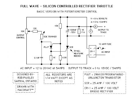
Potentiometer Controlled Silicon Controlled Rectifier Throttle
Published:2013/6/7 21:34:00 Author:muriel | Keyword: Potentiometer Controlled, Silicon Controlled, Rectifier Throttle
View full Circuit Diagram | Comments | Reading(1022)
Silicon Controlled Rectifier Model Railroad Throttles
Published:2013/6/7 21:33:00 Author:muriel | Keyword: Silicon Controlled, Rectifier Model, Railroad Throttles
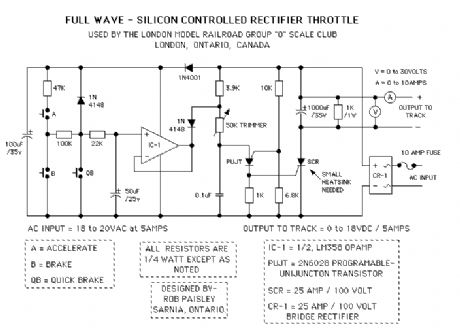
The following is a schematic drawing of a Silicon Controlled Rectifier type throttle for use on larger scale model railroads. Three versions of this throttle are shown on this page. They are not sophisticated designs but work well and are tough and reliable.
It was designed for use on a The London Model Railroad Group's large O scale layout located at London, Ontario, Canada. The prime requirements for the club throttles were that they be rugged, reliable and produce as little heat as possible. Throttles of this type have been in service at the club since 1987 with excellent results. The throttle will deliver 5 amps continuously and up to 18 volts DC. See Notes.
The Programmable Unijunction Transistor used to trigger the SCR is the key to this design as it ensures that the SCR fires on every cycle of the fullwave DC. This gives a very efficient operation with low voltage loss and very little heat generated. Please refer to your electronics books if you need more information on how the SCR and PUJT in the circuit function.
The SCR throttle has momentum effect built in due to the memory provided by the 50uF capacitor at the PLUS input of the OPAMP. There is no decay but this can be added by placing a 1 to 2 Megohm resistor in parallel with the 50uF capacitor. Increasing the value of the memory capacitor will slow the action of the throttle controls.
Due to its unregulated voltage output, the SCR throttle will have a prototypical feel as trains will slow when climbing grades and speed up when going down grades. The operator must work the throttle to keep their train from speeding or slowing too much in hilly terrain.
SCR Throttle Setup Instructions
The 50K Trimmer is adjusted so that maximum output voltage can be obtained but keep the SCR triggering on each cycle. To do this perform the following steps.
1. With no load connected to the throttle output and the AC input turned on.
2. Connect an analog voltmeter to the output of the throttle (0-30V).
3. Set the trimmer to its maximum resistance.
4. Press and hold the ACCELERATE push button until the output voltage stops increasing.
5. DECREASE the resistance of the trimmer until the output voltage peaks and then begins to fall again. When the voltmeter needle starts to bounce slightly the SCR is at its maximum trigger angle. STOP.
6. INCREASE the resistance of the trimmer slightly until the meter needle stops bouncing. At this setting the throttle will be able to deliver its maximum voltage. If the trimmer resistance is set too low the SCR will not trigger on every cycle of the full wave DC at full output voltage and could be damaged by high current spikes.
Notes
* NOTE 1 At full throttle and with no load this circuit will deliver more than 25 volts. Therefore care must be taken with auxiliary equipment and train lighting that may be connected to the track.
(Remember that most voltmeters only indicate average or RMS voltage and not the peak voltage which can be 1.4 times greater that the average.)
* NOTE 2 If your trains will run as fast as you need at lower track voltages than 18 volts then lower the input to 12 or 14 volts AC. The under load DC output voltage of this type of throttle is roughly equal to the RMS AC input voltage.
* NOTE 3 Add your own reversing switches to the output and a suitable circuit breaker for added protection if desired.
* NOTE 4 The use of good quality push buttons is a must as these are the most likely components of the throttle to fail due to the heavy thumbs of some people.
Please feel free to use this design if you wish. It worked for our club it might be useful to you. (View)
View full Circuit Diagram | Comments | Reading(1981)
A Three Terminal Regulator Type Throttle
Published:2013/6/7 21:32:00 Author:muriel | Keyword: Three Terminal, Regulator Type , Throttle
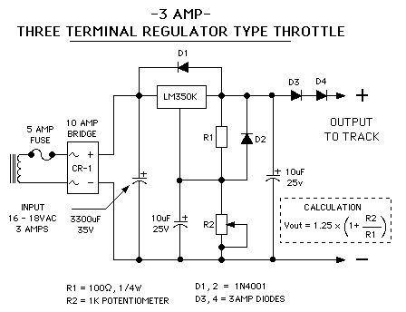
The schematic above is of a Three Terminal Regulator (TTR) design based on the LM350K adjustable voltage regulator which has a 3 Amp current rating as opposed to the LM317K with a 1.5 Amp rating. The LM 350 is internally protected from current and thermal overload and can be thought of as a high current version of the LM 317.
With the component values shown the circuit is designed to have and output voltage range of approximately 1.25 to 13.5 Volts when measured at the output of the regulator. The calculation on the drawing is used to determine the output voltage for given values of R1 and R2.
Because these regulators have a minimum output voltage of 1.25 Volts diodes D3 and D4 will provide a voltage drop of approximately 1.4 Volts so that zero output to the track can be obtained. These diodes need to have at least a 3 amp rating
The diodes D1 and D2 added to the circuit will prevent damage to the regulator during certain adverse conditions such as the output voltage being higher than the input voltage to the regulator. This can happen if this type of circuit is used as a variable power supply for an electronics test bench and without the added protection of D3 and D4.
A substantial heat sink will be needed for the TTR as quite a bit of heat will be generated when drawing high current with low output voltages. For this reason this circuit is not recommended for use in hand held throttles.
If the less expensive LM 317 regulator is used this circuit makes an excellent test bench power supply just leave out D3 and 4 and add a voltmeter. (View)
View full Circuit Diagram | Comments | Reading(1427)
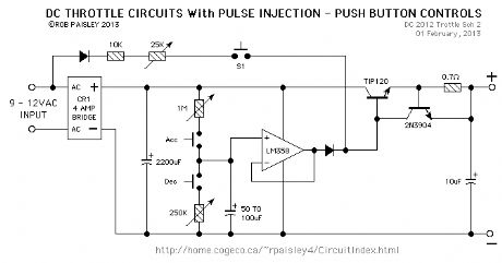
DC Throttle Circuits With Injected Pulses
Published:2013/6/7 21:31:00 Author:muriel | Keyword: DC Throttle Circuits, Injected Pulses
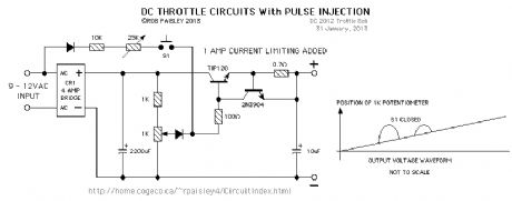
The following circuit is a straight DC version of the fullwave circuits above.
A varialable level, 60Hz pulse injection scheme is also included, this could be used to boost the output voltage in difficult areas of track, used to make the locomotive creep or perhaps as a kicker when shunting.
The same basic throttle as above but with push button controls. (View)
View full Circuit Diagram | Comments | Reading(1471)
basic throttle
Published:2013/6/7 21:30:00 Author:muriel | Keyword: basic throttle
View full Circuit Diagram | Comments | Reading(871)
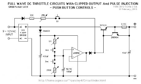
Fullwave DC Throttle Circuits
Published:2013/6/7 21:30:00 Author:muriel | Keyword: Fullwave DC Throttle Circuits
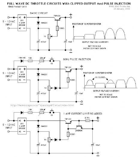
The following circuits are variations of a full wave DC throttles. The output voltage is clipped at a voltage level determined the 1K potentiometer so that the waveform is flat for most of the cycle. These throttles have good slow speed operation for typical DC motors.
A varialable level, 60Hz pulse injection scheme is also included, this could be used to boost the output voltage in difficult areas of track, used to make the locomotive creep or perhaps as a kicker when shunting. (View)
View full Circuit Diagram | Comments | Reading(970)
Full Featured Toy Throttle (Mk II)
Published:2013/6/7 21:29:00 Author:muriel | Keyword: Full Featured Toy Throttle (Mk II)
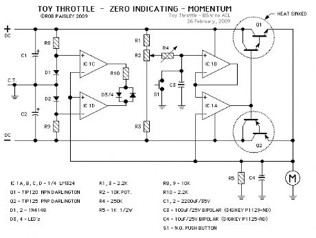
The next schematic shows a full featured Toy Throttle Upgrade. This version has Zero Indication, and Momentum.
The transformer and bridge rectifier have been omitted to make the drawing smaller.
All of the features in this circuit can be found in conventional throttle designs. The only difference here is the PLUS or MINUS output voltage capability. (View)
View full Circuit Diagram | Comments | Reading(856)
Toy Throttle with Zero Indication
Published:2013/6/7 21:29:00 Author:muriel | Keyword: Toy Throttle , Zero Indication
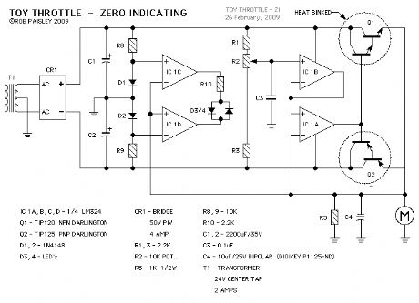
With this type of throttle would be difficult to know when the output is at ZERO . To help with this a ZERO indicator has been added to the next drawing. The indicator can also show the trains direction.
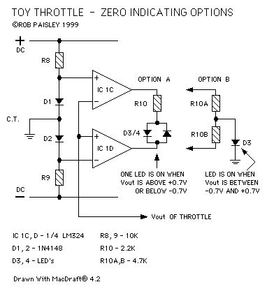
The above schematic shows the addition of a Zero Indicating circuit to the throttle. When the output voltage is between +0.7 and -0.7 Volts both of the LED's, D3/4 will be OFF. As the output voltage increases, either PLUS or MINUS, one of the LED's will turn ON.
This will allow the operator to know when the throttle's output voltage is near ZERO and the train is safely stopped.
As there are two LED's, they can also show the direction of travel based on the polarity of the output voltage.
A two colour LED could be used for D3/4. This will give a GREEN indication for one direction and a RED indication for the other.
The next schematic shows an optional ZERO indication method. In this case the LED will be ON when the throttles output is near ZERO.
(View)
View full Circuit Diagram | Comments | Reading(622)
Basic Toy Throttle
Published:2013/6/7 21:27:00 Author:muriel | Keyword: Basic Toy Throttle

The above schematic shows the basic Toy Throttle. It is powered by a 24 Volts AC, Center Tapped transformer to provide PLUS and MINUS voltages.
The throttle uses a Push-Pull amplifier that eliminates the need for a reversing relay or switch.
When resistor R2 is in the CENTER position the throttles output voltage would be ZERO . Adjusting R2 up or down would produce positive or negative voltage to the track thereby controlling the trains direction.
Resistors R1 and R3 limit the maximum output voltage to between PLUS or MINUS 10 Volts. (View)
View full Circuit Diagram | Comments | Reading(873)
A Regulated Current Pulse Throttle
Published:2013/6/7 21:27:00 Author:muriel | Keyword: A Regulated Current Pulse Throttle
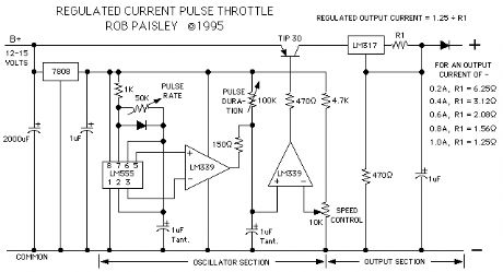
The next throttle is more than a little different, it's very different but in its own unique way it works just fine. It is however posted here for interest sake only and should not be viewed as a major discovery or some sort of magic trick.
The design uses the variable pulse width oscillator that is the at the heart of the Variable Pulse Type Throttle as shown above. The oscillator in this circuit however switches a current regulator constructed from an LM317 voltage regulator.
Rather than regulating the output voltage this throttle instead produces variable width pulses of a fixed current value, for example 200 or 400mA. The voltage can rise to a level that is determined largely by the B+ input voltage and the drop across the LM317 but the motor can only receive the maximum current that the LM317 will pass. This current value is determined by the value of R1. (View)
View full Circuit Diagram | Comments | Reading(822)
| Pages:30/471 At 202122232425262728293031323334353637383940Under 20 |
Circuit Categories
power supply circuit
Amplifier Circuit
Basic Circuit
LED and Light Circuit
Sensor Circuit
Signal Processing
Electrical Equipment Circuit
Control Circuit
Remote Control Circuit
A/D-D/A Converter Circuit
Audio Circuit
Measuring and Test Circuit
Communication Circuit
Computer-Related Circuit
555 Circuit
Automotive Circuit
Repairing Circuit