
Basic Circuit
Index 29
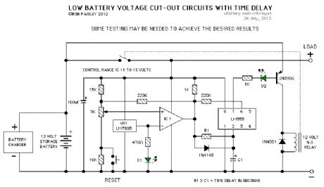
Low Battery Voltage Cutout Circuits 2
Published:2013/6/18 20:51:00 Author:muriel | Keyword: Low Battery, Voltage Cutout Circuits
View full Circuit Diagram | Comments | Reading(872)
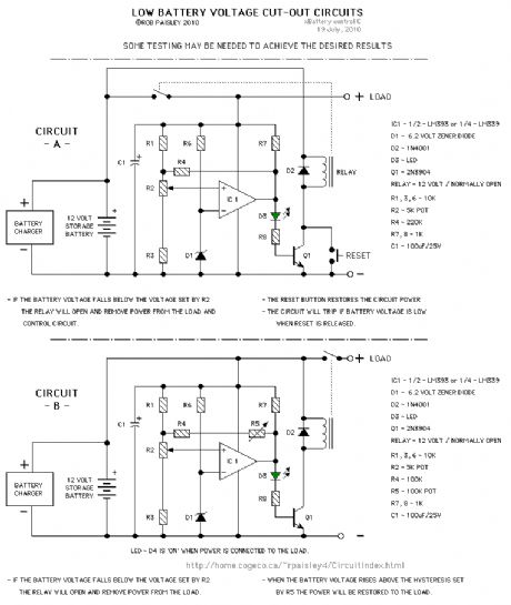
Low Battery Voltage Cutout Circuits
Published:2013/6/18 20:51:00 Author:muriel | Keyword: Low Battery , Voltage Cutout Circuits
View full Circuit Diagram | Comments | Reading(876)
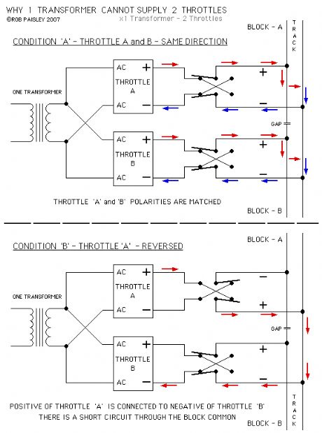
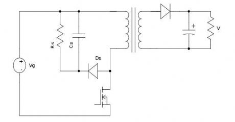
1 Transformer For 2 Throttles schematic
Published:2013/6/18 3:58:00 Author:muriel | Keyword: 1 Transformer, 2 Throttles schematic
View full Circuit Diagram | Comments | Reading(689)
DCC - Zero Stretching Simulator
Published:2013/6/18 3:55:00 Author:muriel | Keyword: DCC - Zero Stretching Simulator
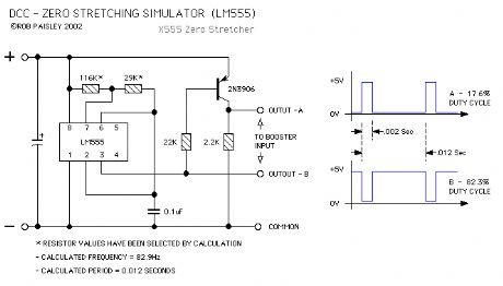
This circuit is designed to simulate the 'Zero Stretching' function of Digital Command Control systems used by model railroads.
This circuit was used drive the booster while testing the operation of block occupancy detectors and DCC signal failure circuits while in the zero stretching mode.
The parts values have been calculated to give the maximum stretching length and ratio allowed for DCC systems. Complimentary outputs, A and B, are provided in order to drive the booster's output polarity stretched in both directions. (View)
View full Circuit Diagram | Comments | Reading(834)
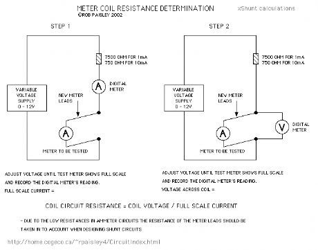
Finding The Resistance Of Meter Coils
Published:2013/6/18 3:55:00 Author:muriel | Keyword: Resistance , Meter Coils
View full Circuit Diagram | Comments | Reading(853)
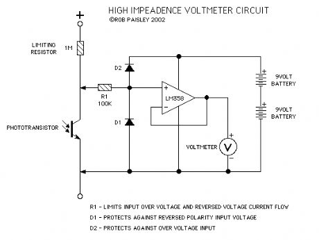
High impedance Test Voltmeter Schematic
Published:2013/6/18 3:54:00 Author:muriel | Keyword: High impedance , Test Voltmeter Schematic
View full Circuit Diagram | Comments | Reading(1773)
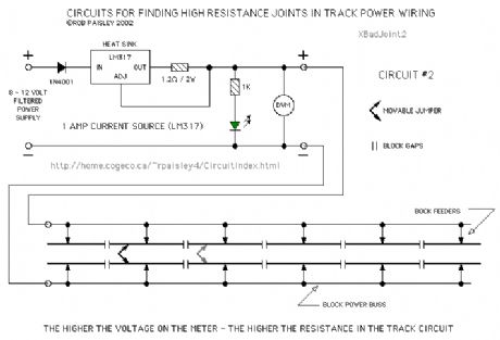
Finding Bad Joints In Track Wiring
Published:2013/6/18 3:53:00 Author:muriel | Keyword: Bad Joints , Track Wiring
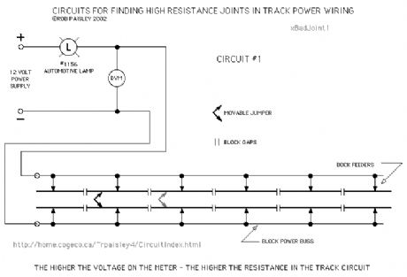
The following is a method of finding high resistances in track power circuits. The digital voltmeter is set to its lowest range and indicates the resistance in the track circuit by measuring the voltage drop in a given section of track.
The movable jumper is connected across individual blocks in turn in order to check each one. A high voltage indicates a bad connection. The jumper must have as low a resistance as possible to avoid false indications
Two versions of the circuit are shown. Both work identically except that the second limits the current to one ampere.
The tester can be connected as far back in the circuit as desired so that toggle switches are also included in the test.
The diagrams show gaps in both rails although this would not normally be the case. The test will still work and might find bad rail joiners as well.
(View)
View full Circuit Diagram | Comments | Reading(688)
Timed DC Throttle
Published:2013/6/18 3:50:00 Author:muriel | Keyword: Timed DC Throttle
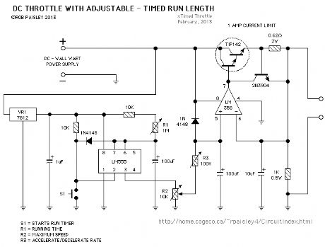
The following is a simple timed DC throttle that has controls for the length of run, accelerate/ decelerate and the maximum train speed. The circuit also has automatic current limiting.
An ideal power supply fo this circuit would be a AC wall adapter. This would likely be less expensive than building a power supply from scratch. The 7812 voltage regulator would not be needed if an adapter with a built in regulator is used.
(View)
View full Circuit Diagram | Comments | Reading(825)
Transformer Secondary Voltage Reduction
Published:2013/6/18 3:44:00 Author:muriel | Keyword: Transformer , Secondary Voltage Reduction
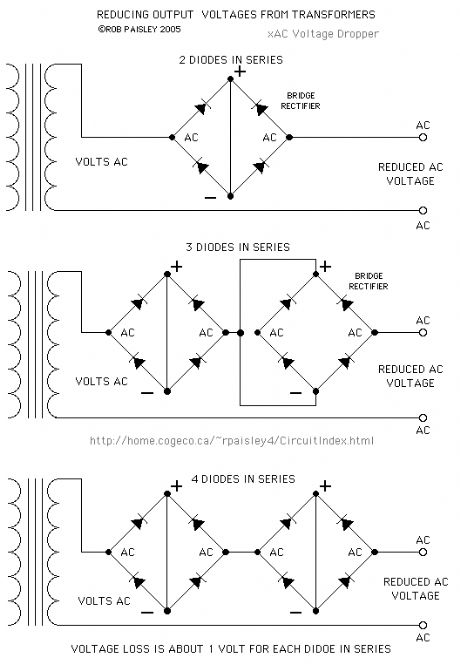
These circuits uses bridge rectifiers to reduce the secondary voltage from transformers. The current rating of the bridges should be 1.5 times the expected maximum current or greater. (View)
View full Circuit Diagram | Comments | Reading(1166)
TSOP4840 Ir Receiver Modules
Published:2013/6/13 21:26:00 Author:muriel | Keyword: TSOP4840 Ir Receiver Modules
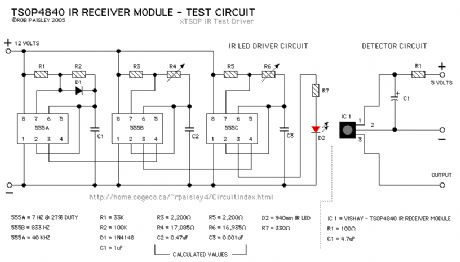
The following diagram is for an oscillator that was used to get the information for Oscillator Output - C as shown above. (View)
View full Circuit Diagram | Comments | Reading(1510)
Ir Receiver Modules
Published:2013/6/13 21:26:00 Author:muriel | Keyword: Ir Receiver Modules
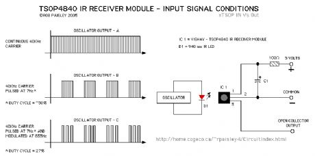
View full Circuit Diagram | Comments | Reading(3036)
Snubber Diodes Across Relay Coils
Published:2013/6/13 21:25:00 Author:muriel | Keyword: Snubber Diodes , Across Relay Coils
View full Circuit Diagram | Comments | Reading(1236)
Full Wave Rectification of DCC Voltages
Published:2013/6/13 21:23:00 Author:muriel | Keyword: Full Wave Rectification , DCC Voltages
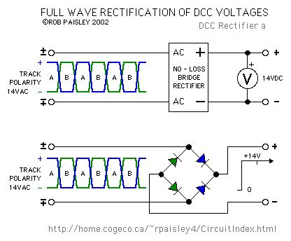
The next diagram shows the effect of rectifying a DCC voltage with a full wave bridge. The voltage at the output of the bridge is equal to the input minus the drop across the diodes.
The small tick in the output of the bridge occurs when the polarity of the H-Bridge reverses. The size of the ticks is largely determined by the efficiencies of the H-Bridge and rectifier bridge and in most cases can be ignored. This is why filter capacitors are not needed for decoders.
Diodes used to rectify DCC should be Schottky or high speed silicon types. Diodes of the 1N4000 and 1N5400 series are not suitable for this application due to their slow turn-off times. (View)
View full Circuit Diagram | Comments | Reading(993)
Adding External Meters to DC Throttles
Published:2013/6/13 21:21:00 Author:muriel | Keyword: Adding External Meters, DC Throttles
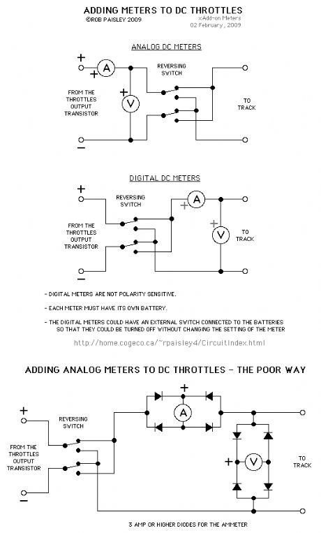
Typical analog meters must be added before the reversing switch. 'Centre zero' meters can be connected after the reversing switch.
Digital meters could easily be added to the output of a DC throttle so that they indicate, volts, current and polarity of the output.
Many digital multimeters are less expensive than analog meters and often easier to find locallys.
Each digital meter must have its own battery or short circuits/sneak current paths will be created between the meters wich could dammage the meters or give false readings.
The battery for the digital multimeters could also be switched by an optoisolator powered from the pack's auxiliary output so that the meters are turned off when the thottle is off.
(View)
View full Circuit Diagram | Comments | Reading(706)
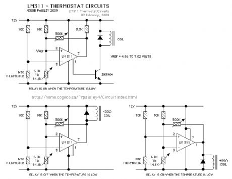
LM311 Tehermostat Circuits
Published:2013/6/13 21:21:00 Author:muriel | Keyword: LM311, Tehermostat Circuits
View full Circuit Diagram | Comments | Reading(1929)
5 Second Ramp Generator for Locomotive Sound Card Demonstration
Published:2013/6/13 21:20:00 Author:muriel | Keyword: 5 Second, Ramp Generator , Locomotive Sound, Card Demonstration
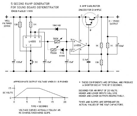
The circuit on this page is designed to produce a timed throttle output for demonstrating on board sound systems in a large scale locomotive.
When a push button is activated the output will rise from 0 to 15 volts in 5 seconds. The voltage will then hold for 5 seconds. The voltage will then return to 0 in about 10 seconds.
When S1 is pushed the 555 timer will start and run for 10 seconds.
For the first 5 seconds the 10 uF capacitor at the PLUS input of the LM 358 or LM324 OPAMP will charge until it reaches the voltage at pin 5 of the 555 timer chip plus 0.7 volts
The voltage across the capacitor will now be steady for 5 seconds.
When the timer shuts off the voltage across the capacitor will decay to 0 over a period of 10 seconds, 5 seconds if the optional diode and resistor are used.
The output of the OPAMP drives a conventional transistor throttle output section.
Notes
The 500K ohm variable resistors are used to adjust the charging rate so that the capacitor at the PLUS input of the OPAMP reaches it maximum voltage (2/3 of the supply - plus 0.7 volts) in 1/2 of the timers output duration. This control could be replaced by a fixed resistor once the required value is determined.
The circuit is designed to produce an output of15 Volts when operated from a well filtered or regulated 20 Volt power supply only. If voltage adjustment is required the value of the 13K ohm resistor can be increased to give a lower output voltage or it can be decreased to give a higher output voltage.
This circuit has no automatic current limiting or overload protection. With a proper supply the circuit will deliver about 2 amps.
A heat sink may be needed for the output transistor.
The parts values shown on the schematic drawing are calculated to give the desired times and output voltages. Due to value tolerances of all of the parts and the leakage currents of the capacitors some adjustment may be required to achieve the desired results. (View)
View full Circuit Diagram | Comments | Reading(1314)
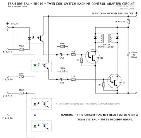
Team digital - SCR16 - Twin Coil Switch Machine Adapter
Published:2013/6/13 21:16:00 Author:muriel | Keyword: Team digital , SCR16 , Twin Coil , Switch Machine Adapter
View full Circuit Diagram | Comments | Reading(952)
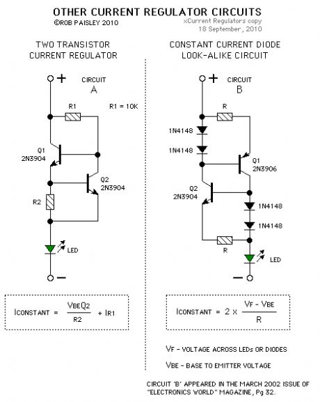
Transistor Based Current Regulators
Published:2013/6/13 1:39:00 Author:muriel | Keyword: Transistor , Based Current Regulators
View full Circuit Diagram | Comments | Reading(1505)
LM317 Current Regulator
Published:2013/6/13 1:39:00 Author:muriel | Keyword: LM317, Current Regulator
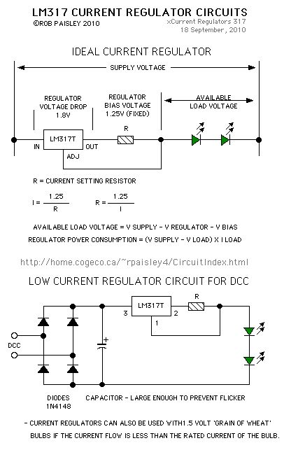
The following is a current regulator built around the LM317 voltage regulator IC. For additional information, see the datasheet for the LM317 series regulators.
(View)
View full Circuit Diagram | Comments | Reading(1468)
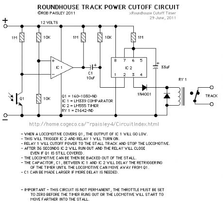
Roundhouse Track Power Cutoff Circuit
Published:2013/6/13 1:27:00 Author:muriel | Keyword: Roundhouse Track , Power Cutoff Circuit
View full Circuit Diagram | Comments | Reading(704)
| Pages:29/471 At 202122232425262728293031323334353637383940Under 20 |
Circuit Categories
power supply circuit
Amplifier Circuit
Basic Circuit
LED and Light Circuit
Sensor Circuit
Signal Processing
Electrical Equipment Circuit
Control Circuit
Remote Control Circuit
A/D-D/A Converter Circuit
Audio Circuit
Measuring and Test Circuit
Communication Circuit
Computer-Related Circuit
555 Circuit
Automotive Circuit
Repairing Circuit