
Relay Control
Index 4
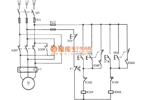
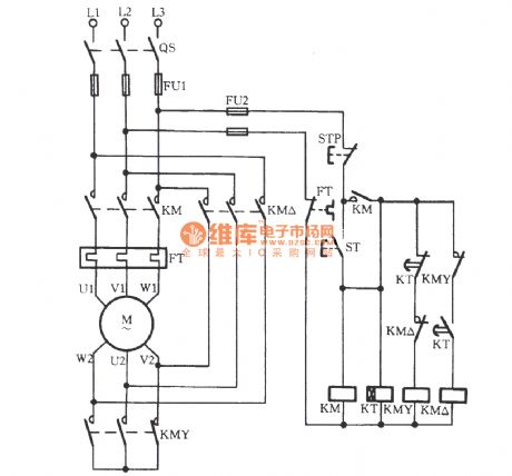
Y-connection three-phase motor low speed running and braking in reverse circuit
Published:2011/7/14 20:29:00 Author:Lucas | Keyword: KMF, three-phase motor
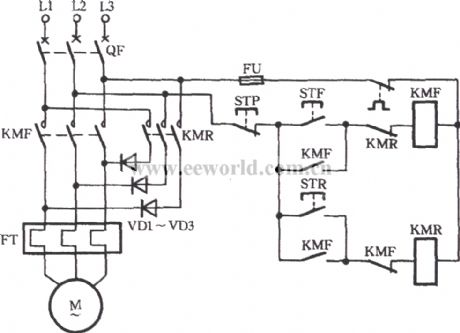
Just as shown in the circuit, high-power semiconductor diode is used for lowering pressure to achieve the low-speed operation of the electric motor. When STF is pressed, AC contactor KMF pulls with the gain of electricity and the motor M runs forward. When STP is pressed, the motor M would power off. If STR is pressed at this time, diode VD1 ~ VD3 are inducted by the reverse contactors KMR. And the power is rectified. The DC current is input to three-phase stator winding. When the M does not turn, press STP for braking the M. If the motor is expected to run in alt= Y-connection three-phase motor low speed running and braking in reverse.
(View)
View full Circuit Diagram | Comments | Reading(4865)
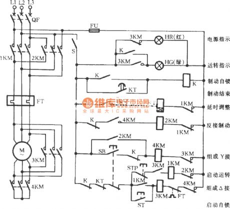
Y-shaped three-phase motor reverse brake circuit
Published:2011/7/14 20:30:00 Author:Lucas | Keyword: three-phase motor, 3KM
View full Circuit Diagram | Comments | Reading(1103)
Three-phase motor for jog brake circuit(a)
Published:2011/7/14 20:31:00 Author:Lucas | Keyword: KT2, Three-phase motor, jog brake
Many mechanisms not only require fast and correct parking, but also require jog brake. In order to improve the efficiency and positioning accuracy, the three-phase motor for jog brake circuit is used.
(View)
View full Circuit Diagram | Comments | Reading(1282)
Three-phase motor dual-speed 2Y / △ connection speed control circuit (c)
Published:2011/7/14 20:33:00 Author:Lucas | Keyword: Three-phase motor, 2Y / △ connection
View full Circuit Diagram | Comments | Reading(4034)
Three-phase electric dual-speed 2Y / △ connection speed control circuit(b)
Published:2011/7/14 20:32:00 Author:Lucas | Keyword: dual-speed 2Y / △ connection

View full Circuit Diagram | Comments | Reading(1122)
Three-phase motor contactor interlock action for switching circuit
Published:2011/7/10 22:26:00 Author:Lucas | Keyword: Three-phase motor, contactor interlock
The circuit which uses contactor interlock for switching is shown. The STF and STR respectively refer to positive and reverse button. SB and SB2 are respectively positive and reverse jog buttons. And SB1 and SB2 are respectively equipped with a composite button. The dashed line in the figure indicates that the two contacts are the same button. For example, when the button SB1 is pressed, the motor would jog to run with the broken of the normally closed contacts.
(View)
View full Circuit Diagram | Comments | Reading(3988)
Two electric motors one after one start-up circuit
Published:2011/7/10 20:18:00 Author:John | Keyword: electric motor, motor, one after one start-up
Procedures: Firstly, the starting button ST1 of the motor M1 is pressed to lead the KM1 coil to be energized. When the main contacts are closed, the motor M1 is launched to be self-locked. And the other pair of normally opening contact closes to induct the line circuit between KM2 and FT2. Then, press the starting button ST2 of the motor M2. The AC contactor KM2 would be powered to drive the electric motor M2 to start.
(View)
View full Circuit Diagram | Comments | Reading(2158)
LK001 selection frequency music outlet circuit
Published:2011/7/10 20:16:00 Author:John | Keyword: selection frequency music outlet

The circuit is as shown. It includes sound sensor BM, voice controlled IC, thyristor control circuit, imitation sound circuit and AC step-down rectifier circuit. Voice-specific integrated circuit LK001 is the core device of the circuit, whose internal function block circuit is shown.
(View)
View full Circuit Diagram | Comments | Reading(778)
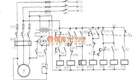
UPS instantly switching Y-△ starting circuit
Published:2011/7/10 20:20:00 Author:John | Keyword: KM4, Y-△ starting
As for conventional Y-△ starting motors, when the motor shifts from a Y-shaped to △ running, phase short circuit often occur. In order to prevent phase short circuit, motor winding generator usually occur with power outages, thus inevitably for the formation of a strong secondary impact of current for the grid and the motor itself. The circuit is shown, which can achieve the uninterruptible power supply during the operation of shifting from Y-shaped to △ running. Besides, the voltage of the motor winding is not the line voltage which is directly from the Y-phase voltage to start operation of the △-shape. Actually, it has gone through a transition to an intermediate voltage level.
(View)
View full Circuit Diagram | Comments | Reading(1698)
zero sequence current protection with ultilizing third harmonic pressure velocity saturation circuit
Published:2011/7/10 20:19:00 Author:John | Keyword: current protection, third harmonic pressure velocity saturation

The shown circuit is suitable for △ or Y-shaped connection of the three-phase motor with rather great capacity. Off phase is to adopt a speed differential current transformer saturation TA, whose primary side is connected to the main circuit in series and secondary side’s head and tail is connected in series to form the open triangle. At the moment that the three-phase supply current (equal) is symmetrical, third harmonic voltage generated by TA is gone through the rectifier VC and the filtering capacitor C. So the sensitive K relay takes action to drive the motor M to run normally. When there is one phase is off, the remaining two-phase’s line current is with contrasting phase. And their synthetic current is zero for releasing the K and disconnecting the main circuit of the motor.
(View)
View full Circuit Diagram | Comments | Reading(1357)
two motors for sequential starting circuit
Published:2011/7/10 20:19:00 Author:John | Keyword: motor, sequential starting
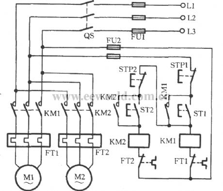
Some production machines have two or more electric motors, because these motor play different roles in the circuit. Sometimes, a certain sequence must be conformed to start in order, thus ensuring the normal production. The used circuit is shown in the figure. Take the two electric motors M1 and M2 used here for example. When the ST1 is pressed, KM1 coil is energized. And the coil’s main contacts and auxiliary contacts take action. And the motor M1 launches to be self-locked. It is obvious that KM1’s closure contact would not be self-locked if the ST2 is pressed firstly rather than the motor M1 (that is the ST1). Beside, KM2 coil would be in power shortage and be not able to start the motor M2.
(View)
View full Circuit Diagram | Comments | Reading(13783)
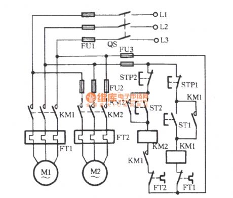
two electric motors for sequential parking circuit
Published:2011/7/10 20:19:00 Author:John | Keyword: electric motor, sequential parking
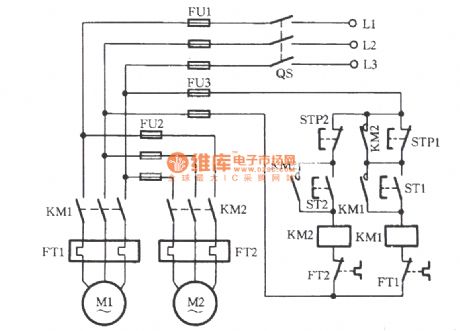
In some working procedures, it is required to part the first motor and followed to park another motor. The figure shows the circuit of adapting to run the program. When the starting button ST1 is pressed, motor M1 operates. Then, the ST2 is pressed to pull KM2, leading to the operation of motor M2. Due to the KM2's pull, its normally opening contact is self-locked and the other contact closes to short the stop button STP1. Therefore, if the STP1 is pressed by mistake, KM1 will not lose power and release it. And the motor M1 will not stop at this time. Only the STP2 is pressed firstly to stop the motor M2 can the KM2 lose power. Then, its normally opening contacts release. Only under this situation can it is possible to stop M1 by pressing STP1.
(View)
View full Circuit Diagram | Comments | Reading(2359)
TWH8778 radio automatic shutdown circuit
Published:2011/7/7 7:09:00 Author:Fiona | Keyword: radio automatic shutdown, sound signal
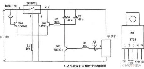
The circuit mainly uses a new type of power switching device TWH8778.It produces simply and has no debugging.TWH8778 shape and the function of the pins is shown as above,the ⑤ pin is control side,when the pin's voltage is higher than the cut-in voltage (about 1.6V), the electronic switch is closed, ①, ② pins are connected. When touching the contact of the touch switch between BG1 and the power,BG1 is conducted,the voltage drop of R1 makes TWH8778 close,the recorder works normally due to the power is connected.If the recorder is on playback, thesound signal is coupled by C3 to the base of BG3 to make BG2 conduct,BG2 has a base current and it is in the conduction state,the voltage drop of R1 makes TWH8778 close again. (View)
View full Circuit Diagram | Comments | Reading(922)
Starting insurance for starting injection and running out circuit
Published:2011/7/5 10:32:00 Author:John
Three-phase motor’s starting current is large, which is generally three times more of the motor’s rated current. If the chosen fuse (also known as fuse) is with a larger rated current, it is rater detrimental to the protection for the motor. The phenomenon of frequent burning of insurance frequently occurs even if it is in the right size. The circuit as shown can be used to resolve this contradiction. As for the figure, FU1 is the motor main fuse with the right size and FU2 is a launching insurance. Rated current of FU1 should be equal to the motor’s rated current. And rated current of FU2 is generally equals to that of the FU1.
(View)
View full Circuit Diagram | Comments | Reading(845)
Exhaust fan automatically starting circuit
Published:2011/7/5 8:56:00 Author:John | Keyword: Exhaust fan
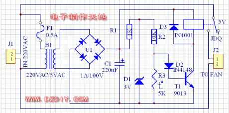
The circuit is as shown. 220-volt power supply is divided into two routes. One route is transferred into a 5V power supply through the transformer, aiming to supply the control circuit. The other route is connected to the exhaust fan through the relay in series. As for control circuit, the 5-volt power supply gets DC power supply through the rectifier. Commonly, R3, the partial pressure of R3 can not be the transistor due to a smaller resistance. So the relay is not energized and the exhaust fan does not work. When the heater is heated, heat resistance of R3 becomes larger. And the partial pressure on the R3 would induct the transistor. Then the relay pulls and exhaust fan works. (View)
View full Circuit Diagram | Comments | Reading(1649)
three contactors for consisting Y-△ buck starting circuit
Published:2011/7/10 3:09:00 Author:Lucas | Keyword: contactor
View full Circuit Diagram | Comments | Reading(747)
Three-phase motor dual-speed 2Y / △ connection with indicator regulator circuit
Published:2011/7/10 2:46:00 Author:Lucas | Keyword: Three-phase motor, indicator
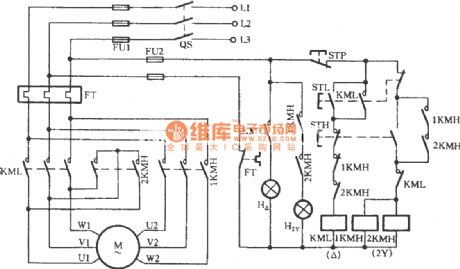
The circuit increases the low speed indicator H △ and high-speed indicator H2Y. When the motor stops, the two lights are not lighted.
(View)
View full Circuit Diagram | Comments | Reading(8292)
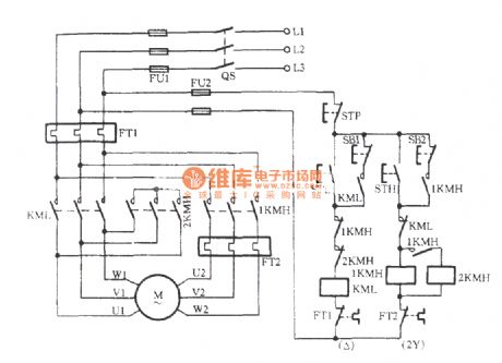
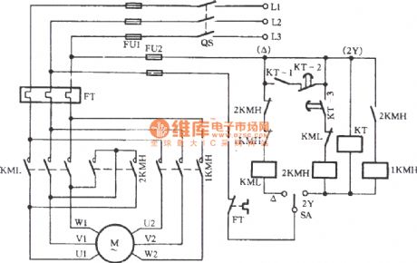
Three-phase motor dual-speed 2Y / △ connection speed control circuit (a)
Published:2011/7/10 2:54:00 Author:Lucas | Keyword: 2KMH, Three-phase motor, 2Y / △ connection
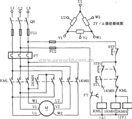
There are three AC contactors used in the circuit. The button STH is the high-speed control button. When it is pressed, AC contactor 1KMH and 2KMH suctions at the same time, thus driving the motor M for high-speed (2Y) operation. The button STL is the low-speed control button. When it is pressed, AC contactor KML suctions to drive the motor M for low-speed (△) operation. When the button STP is pressed, the motor stops running. FT is a thermal relay for overload protection.
(View)
View full Circuit Diagram | Comments | Reading(12144)
Three-phase motor dual-speed 2Y / △ connection automatic speed control circuit
Published:2011/7/10 2:56:00 Author:Lucas | Keyword: Three-phase motor, 2Y / △ connection
View full Circuit Diagram | Comments | Reading(4494)
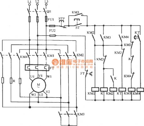
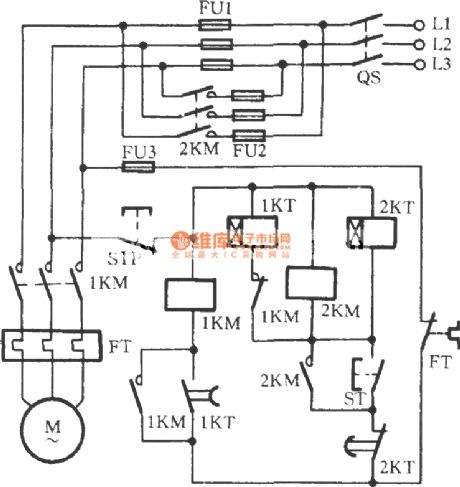
△-shaped three-phase motor buck starting circuit
Published:2011/7/10 3:07:00 Author:Lucas | Keyword: three-phase motor

The start button ST is pressed to drive the 1KM coil to gain electricity and to be self-protected. At the same time, 3KM relay coil KT gains electricity and motor’s windings are connected to form a extending triangle for buck starting. When the Kt's tuning time reaches, the delaying normally closed contacts disconnect. Then the 3KM coil releases with the loss of power and its normally closed auxiliary contact is closed. Meanwhile, KT’s delaying closing normally opened contacts are closed. The 2KM coil gains electricity to suction and to be self-locked. 3KM’s main contact releases while 2KM’s main contact closes. Then the motor windings are transferred from extending triangle shape into a triangle connection. The starting process is over and the operation is on.
(View)
View full Circuit Diagram | Comments | Reading(2044)
| Pages:4/8 12345678 |
Circuit Categories
power supply circuit
Amplifier Circuit
Basic Circuit
LED and Light Circuit
Sensor Circuit
Signal Processing
Electrical Equipment Circuit
Control Circuit
Remote Control Circuit
A/D-D/A Converter Circuit
Audio Circuit
Measuring and Test Circuit
Communication Circuit
Computer-Related Circuit
555 Circuit
Automotive Circuit
Repairing Circuit