
Relay Control
Index 5
Three-phase motor for extend the △ access to single-phase operation circuit
Published:2011/7/9 9:34:00 Author:Lucas | Keyword: Three-phase motor
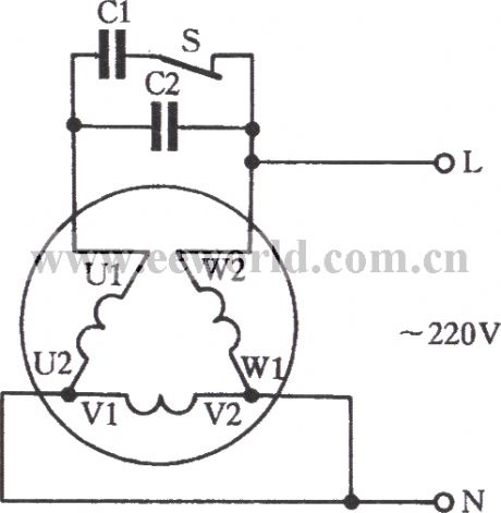
Extension three-phase motor with △-connection is suitable for 220V or 380V single-phase power operation. The circuit is shown below. The principle of this connection is the same to that of Y-connection, but there are some differences either. (1) It can be seen from the figure that only one U phase-phase winding is the main winding among the motor windings. And the V phase and W phase are connected in series as auxiliary windings. (2) Winding U and winding V, W form an autotransformer. Due to the boosting function of the autotransformer, capacitors C1 and C2 are exposed to bear voltage which is three times of that of the single-phase power supply. As a result, a capacitor with a high working voltage is needed to be used, such as a capacitor of 1000V.
(View)
View full Circuit Diagram | Comments | Reading(2353)
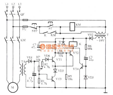
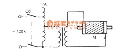
three-phase motor with 36V low-voltage control circuit
Published:2011/7/10 2:36:00 Author:Lucas | Keyword: three-phase motor
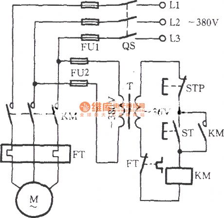
Just as shown in the circuit, the motor is a full-voltage direct starting circuit. And its control circuit’s power supply is the AC voltage reduced by the transformer T from 380V to 36V. Therefore, the AC contactor’s coil voltage must be 36V. In wet or such situations, the security has been ensured.
(View)
View full Circuit Diagram | Comments | Reading(3396)
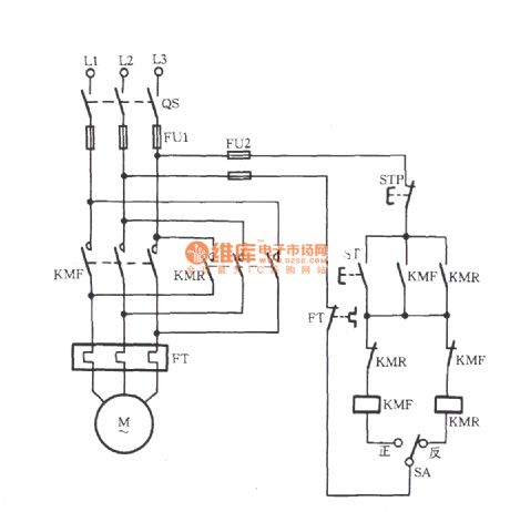
reversible controlling point of the three-phase motor short brake circuit
Published:2011/7/9 9:47:00 Author:Lucas | Keyword: three-phase motor
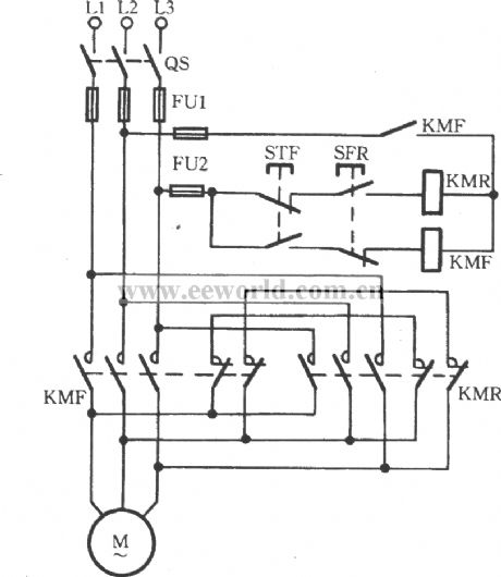
The circuit is shown. When STR is pressed, the reverse contactor KMR pulls to disconnect the braking short contacts (KMR’s normally closed contacts), thus driving the motor to run reversely. When STR is released, the contactor releases with the loss of power. And the main contact KMR is off. At this time, braking short contacts restore the closed state to drive the stator coil to produces the M braking torque for braking. Similarly, forward braking operation is done with the same methods and principles as described above. This brake circuit is only applies for small motors below 3kW.
(View)
View full Circuit Diagram | Comments | Reading(2169)
Three-phase motor contactor button interlock action for switching circuit
Published:2011/7/9 10:48:00 Author:Lucas | Keyword: Three-phase motor, contactor button, interlock
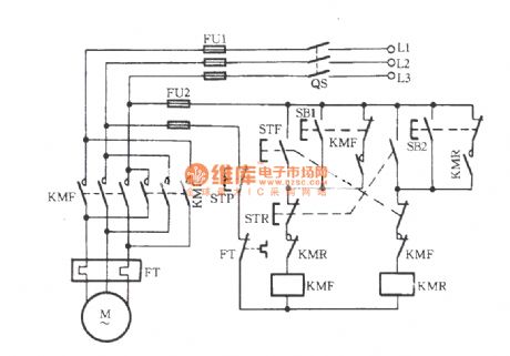
Just shown in the figure, STF, STR, SB1 and SB2 all are composite buttons. STF and STR are respectively positive and reverse button, which operate along with the contactor’s auxiliary contacts for achieve interlock action. SB1 and SB2 both are jog buttons. (View)
View full Circuit Diagram | Comments | Reading(3577)
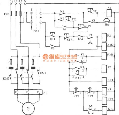
Three-phase motor intermittent starting circuit
Published:2011/7/10 2:29:00 Author:Lucas | Keyword: Three-phase motor
View full Circuit Diagram | Comments | Reading(1173)
Three-phase motor self-motivation brake circuit
Published:2011/7/10 2:22:00 Author:Lucas | Keyword: Three-phase motor, KM2
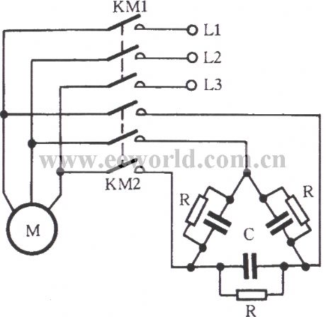
Just as shown in the figure, RC components are connected to stator windings during the free braking so as to form a self-motivation brake circuit. 2KM is closed when the KM1 is off. At this moment, the stator’s remanence induction would generate a capacitive current by RC circuit. It will strengthen the rotor’s remanence magnetic created by its magnetic. The brake torque is formed for braking the motor at high speed. RC circuit’s connection should be done according to the winding connection of the three-phase stator. It is tested that RC with Y connection circuit is suitable for Y-connection motor.
(View)
View full Circuit Diagram | Comments | Reading(2961)
Simple three-phase motor short braking circuit
Published:2011/7/10 0:25:00 Author:Lucas | Keyword: three-phase motor, KM1
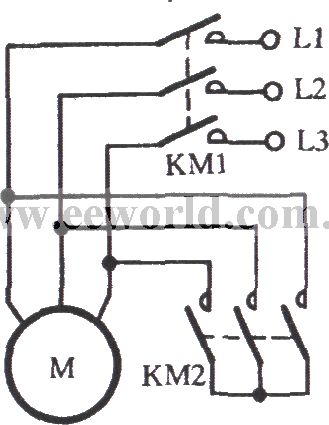
The stator windings maintain the opening state at this moment. The EMF does not produce current and dose not produce braking torque. Thus it is called free brake. If the stator winding is disconnected from the grid as shown in the figure and is short connection by KM2, the remanence potential of the stator windings can be generated to produce current. And the resulting braking effect is called short brake”. When the 5.5kW motor short-circuit brakes, short-circuit current is with duration of 100 milliseconds. It is better than free braking, whose braking time is 3 / 4 of the free braking time.
(View)
View full Circuit Diagram | Comments | Reading(1661)
Three-phase motor for jog brake circuit(b)
Published:2011/7/10 1:18:00 Author:Lucas | Keyword: Three-phase motor, jog brake
View full Circuit Diagram | Comments | Reading(2237)
Three-phase motor phase-off protection circuit
Published:2011/7/10 1:21:00 Author:Lucas | Keyword: VD1, Three-phase motor
View full Circuit Diagram | Comments | Reading(1004)
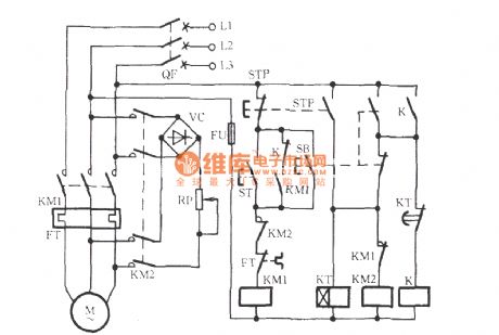
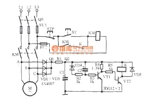
Three-phase motor phase-off over-current protection circuit
Published:2011/7/10 1:36:00 Author:Lucas | Keyword: VD5, Three-phase motor
The figure shows a rather practical circuit. When ST is pressed, KM pulls to start the motor M. The current transformer TA output current through the secondary side. The current forms a voltage signal through the VD1 rectifier and partial pressure by RP and R1. The voltage signal is added to the base VT1 through R2 and VD6. The other signal VT3 added to the base through RP. VT1, VT2 and VT3 form an emitter coupled bitable circuit. During the normal operation, VT1 ends and VT2 and VT3 are saturated to conduct. Then the relay K pulls to drive the motor M to run normally.
(View)
View full Circuit Diagram | Comments | Reading(3137)
Three-phase motor for against phase-phase short circuit commutation circuit
Published:2011/7/10 1:57:00 Author:Lucas | Keyword: Three-phase motor, phase-phase short circuit
During the revering of the motor, the contactor’s main contacts may cause rather serious arcing phenomenon due to operation or for some other reasons. If the arc has not been completely extinguished, the reverse AC contactor pulls to cause phase-phase short circuit. Just as shown in the circuit, an AC contactor KM is used to solve the phase-phase short circuit. During the reversing process of positive and negative, the forward contactor KMF powers off. And the contactor KM (that is the additional one) also disconnect. Therefore, four break interrupters are created. It can effectively extinguish the arc and avoid the phase-phase short circuit failure.
(View)
View full Circuit Diagram | Comments | Reading(1042)
Three-phase motor used for asynchronous generator load distribution circuit
Published:2011/7/10 2:04:00 Author:Lucas | Keyword: 2QS2, Three-phase motor, asynchronous generator
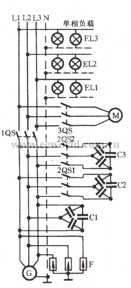
The figure shows the circuit which is applied to distribute the load with small capacity. At this moment, the main capacitor C1, auxiliary capacitor C2 and compensation capacitor C3 are installed on the power distribution screen of the induction generator. The screen is also equipped with lightning protection and over-voltage device. That is the surge arrester.
(View)
View full Circuit Diagram | Comments | Reading(1220)
Three-phase motor with pre-selection switch commutation circuit
Published:2011/7/10 2:10:00 Author:Lucas | Keyword: Three-phase motor, pre-selection switch
Just as shown in the figure, a selector switch SA (which is available of transfer switch, toggle switch, etc.) is used. Before the boot, select positive to start the motor by turning in forward rotation. Instead, select negative to start the motor to run in reverse.
(View)
View full Circuit Diagram | Comments | Reading(4362)
examination to broken rotor bar of three-phase motor
Published:2011/7/10 2:25:00 Author:Lucas | Keyword: rotor, three-phase motor
View full Circuit Diagram | Comments | Reading(856)
Three-phase motor for single-line remote commutation circuit
Published:2011/7/10 0:11:00 Author:Lucas | Keyword: Three-phase motor, single-line remote commutation
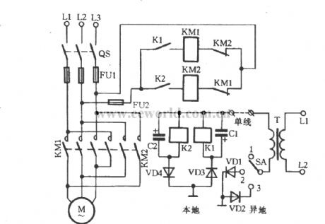
In some cases, it is needed to control motor’s starting-stopping and switching operation far away from the motor. The circuit designed for meeting this requirement is shown in the figure. Set up a wire (single wire) just as shown in the figure and select the “remote control selector switch SA. When the SA is at the position 1 , the local motor stops working. When the SA is at the position 2 , the local relay K1 creates the loop by passing through VD3, ground, VD1, SA and transformer T. When the K1 takes action, its contact connects to coil circuit of the AC contactor. And the motor transfers to run forward.
(View)
View full Circuit Diagram | Comments | Reading(3674)
Three-phase motor with a relay for inverting circuit
Published:2011/7/9 23:59:00 Author:Lucas | Keyword: Three-phase motor, relay
K relay is used to extend switching time for forward and reverse steering. As a result, it can avoid simultaneous suction of KMF and KMR on the reverse run. It also increases the chain reliability between the contactor and the button.
(View)
View full Circuit Diagram | Comments | Reading(1362)
Three-phase motor using limit switch for automatically stopping inverting circuit
Published:2011/7/9 23:50:00 Author:Lucas | Keyword: Three-phase motor, limit switch
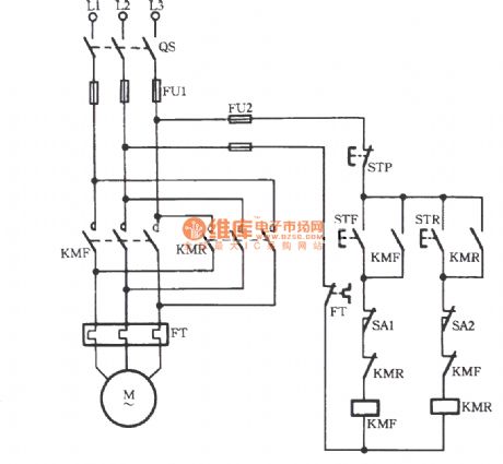
As shown in the figure, limit switches SA1 and SA2 are used to achieve the control for automatically stopping the forward and reverse running. When the mechanical impact block is driven by the motor to hit the SA1 or SA2, it means that it is equivalent to have pressed the stop button. Then the contactor KMF or KMR lose power to stop the motor.
(View)
View full Circuit Diagram | Comments | Reading(12083)
Three-phase motor using the limit switch for inverting circuit
Published:2011/7/9 23:27:00 Author:Lucas | Keyword: Three-phase motor, limit switch
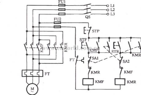
As shown in the figure, two limit switches SA1 and SA2 are used to achieve the automatic control of reciprocation. It utilizes the use of motor to drive mechanical impact limit switch SA1 to achieve forward run’s self-closing (KMF’s off). Meanwhile, the closure for SA1’s interlocking contact is to achieve reversal self-opening (KMR’s closure). And vice verse.
(View)
View full Circuit Diagram | Comments | Reading(3928)
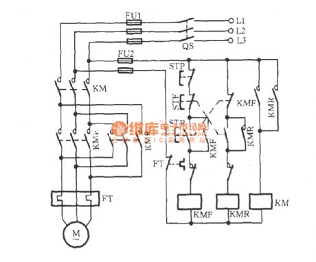
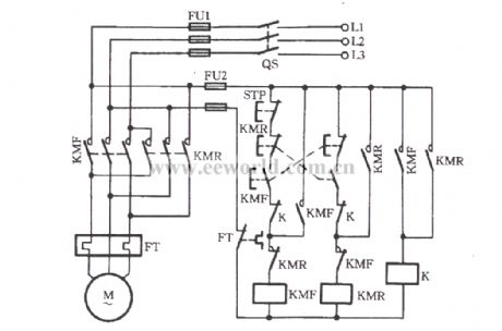
Three-phase motor using three-contactor for inverting circuit
Published:2011/7/9 23:18:00 Author:Lucas | Keyword: Three-phase motor, three-contactor
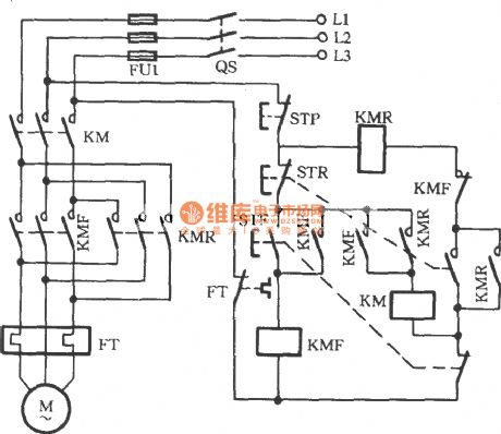
Just as shown in the circuit, the three AC contactors named KMF, KMR and KM are used, which means that each time breaking the motor, the main contact point would grow to four off-points (that is two contacts more than that of the two-contactor). Therefore, it can effectively extinguish the arc of the contactor and can prevent arcing fault.
(View)
View full Circuit Diagram | Comments | Reading(2023)
Three-phase motors for jog commutation circuit
Published:2011/7/10 1:08:00 Author:Lucas | Keyword: Three-phase motor, jog commutation
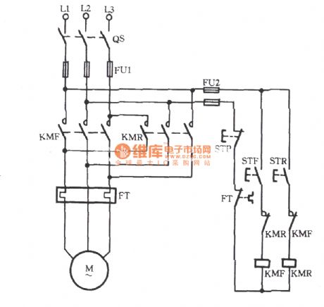
Just shown in the figure, the left circuit is the primary circuit (main circuit) and the right circuit is the secondary circuit (control circuit, the operating circuit). FT is the thermal relay. When STF is pressed, the AC contactor KMF pulls to drive the main contacts of KMF to take action. Then the motor rotates forward (forward). When STF is released, the motor stops working. It is called forward jog . When STR is pressed, KMR pulls to drive the main contact of KlMR to take action. Then the motor rotates in reverse (reverse). When the STR is released, the motor stops rotating. So it is called reverse jog.
(View)
View full Circuit Diagram | Comments | Reading(3356)
| Pages:5/8 12345678 |
Circuit Categories
power supply circuit
Amplifier Circuit
Basic Circuit
LED and Light Circuit
Sensor Circuit
Signal Processing
Electrical Equipment Circuit
Control Circuit
Remote Control Circuit
A/D-D/A Converter Circuit
Audio Circuit
Measuring and Test Circuit
Communication Circuit
Computer-Related Circuit
555 Circuit
Automotive Circuit
Repairing Circuit