
Index 260
Agricultural Automatic Water Feeder (14)
Published:2011/5/22 20:35:00 Author:Sue | Keyword: Agricultural Automatic Water Feeder
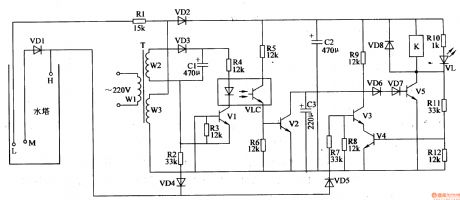
When there is no water, VD4 VD4 V1-V4,VLC are disconnected. VD6 VD7 and V5 are connected and M begins to work and feed water. VL is illuminated.
When the level reaches M, VD5 is connected. V3 has high level. V4,V3 are disconnected and M keeps on working.
When the level reaches H, V5 is disconnected and VL goes out. K is released and M stops working.
When the level is lower than H, VD4,V1,VLC and V2 are disconnected and V4 is connected. V5 is disconnected.
When the level is lower than M, V5 is connected and K is connected. VL is illuminated and M begins to feed water again. (View)
View full Circuit Diagram | Comments | Reading(586)
Agricultural Automatic Water Feeder (13)
Published:2011/5/22 20:30:00 Author:Sue | Keyword: Agricultural, Automatic, Water Feeder
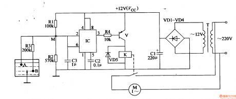
When the level is lower than B, IC's 2 pin has high level and IC's inside trigger reverses. 3 pin outputs low level. V is connected and K is connected. M begins to work and feed water.
When the level reaches b, IC's 2pin has a voltage of Vcc/2, the trigger remain what it is and M keeps on working.
When the level reaches A, IC's 2 pin has low level and 3 pin output high level, V is disconnected and K is released. M stops working. (View)
View full Circuit Diagram | Comments | Reading(652)
Agricultural Automatic Water Feeder (12)
Published:2011/5/22 20:26:00 Author:Sue | Keyword: Agricultural, Automatic, Water Feeder
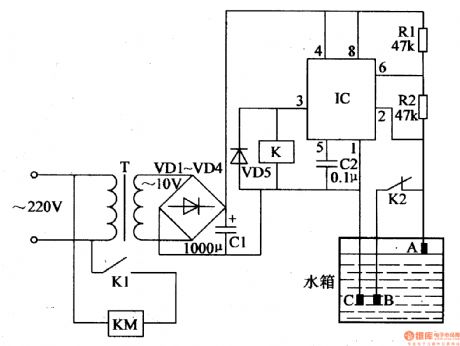
When the level is lower than b, IC's 2 pin is high level and 3 pin outputs low level. K is connected and K1 is connected. K2 is disconnected and KM is connected. M begins to feed water.
When the level reaches A, IC's 2 pin becomes low level and 3 pin outputs high level. K is released and K1 is disconnected. K2 is connected and KM is disconnected. M stops working.
When the level is lower than b, IC's 2 pin becomes high level and 3 pin output low level. K and KM are connected and M begins to feed water again. (View)
View full Circuit Diagram | Comments | Reading(651)
Agricultural Automatic Water Feeder (11)
Published:2011/5/22 20:23:00 Author:Sue | Keyword: Agricultural, Automatic, Water Feeder
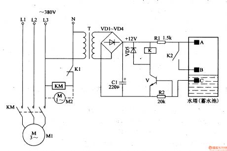
When the level is lower than b, V is disconnected and K doesn't work. Its K2 is disconnected and K1 is connected. M begins to feed water.
When the level reaches A, +12V voltage is put on V, making V connected. K begins to work. Its K is disconnected and K2 is connected. M stops working.
When the level is lower than B, V is disconntected and K is released. K2 is disconnected and K1 is connected. KM is connected and M begins to work again.
The circuit works like this and feed water automatically. (View)
View full Circuit Diagram | Comments | Reading(597)
Electronic Pest Killing Lamp (8)
Published:2011/5/20 4:53:00 Author:Sue | Keyword: Electronic, Pest, Killing, Lamp
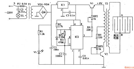
Working Principle:
As seen in the figure 4-187, the circuit consists of power circuit, pulse oscillator and high voltage generator.
The power circuit consists of S,FU,TI,VD1-VD4,C1,C3,IC1,R1 and VL.
The pulse oscillator consists of IC1,R2,R3,RP1 and C2.
The high voltage generator consists of V1,V2,RP2,RP3,R4,R5,T2.
EL is the trap lamp and C5 is reduction voltage capacitor.
When S is on, 220V voltage will illuminate EL. The other circuit will provide the pulse oscilator and high voltage generator with +12V working power after reduction, rectification, filtering by T1,VD1-VD4,C1. The voltage which is rectified will illuminate VLA. (View)
View full Circuit Diagram | Comments | Reading(2960)
Electronic Pest Killing Lamp (7)
Published:2011/5/20 4:44:00 Author:Sue | Keyword: Electronic, Pest, Killing, Lamp
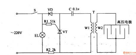
As seen in the figure 4-186, the circuit consists of power switch S, trap light EL, diode VD, thyristor VT, resistor R1 R2, capacitor C, pulse high voltage transformer T and high voltage electrode.
When S is connected, 220V voltage will illuminate EL. The other circuit will provide the pulse oscillator circuit with working voltage. VT will be connected intermittently. T will generate 10kV pulse high voltage which will kill the pest that touches the electric net. (View)
View full Circuit Diagram | Comments | Reading(1031)
Electronic Pest Killing Lamp (6)
Published:2011/5/20 4:36:00 Author:Sue | Keyword: Electronic, Pest, Killing, Lamp
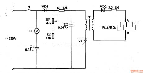
When the power is on, alternating current 220V voltage will illuminate EL after the voltage is reduced by C1. The other circuit will provide VT's positive pole with working voltage, making VT work in the positive half period and stop working in the negative half period. T will generate pulse high voltage which will be put on the high voltage electric net after the voltage is rectified and reduced by VD2 and R3. When the pest touches the net, it will be killed by the high voltage. (View)
View full Circuit Diagram | Comments | Reading(722)
Electronic Pest Killing Lamp (5)
Published:2011/5/20 4:28:00 Author:Sue | Keyword: Electronic, Pest, Killing, Lamp
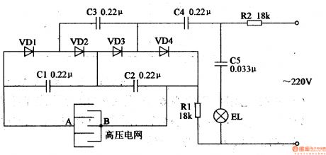
The circuit consists of resistor R2, capacitor C5 and trap lamp EL.
The high voltage generator consists of resistor R1, capacitor C1-C4, diode VD1-VD4 and high voltage electric net.
When the 220V voltage is put on EL, it will make EL illuminated. The other circuit will generate direct current high voltage which will be put on A,B. When the pest touches EL, it will be killed by the high voltage. (View)
View full Circuit Diagram | Comments | Reading(1217)
Electronic Pest Killing Lamp (4)
Published:2011/5/20 4:24:00 Author:Sue | Keyword: Electronic, Pest, Killing, Lamp
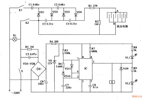
220V voltage will provide the circuit with +12V working power.
When IC begins to oscillate, its 3 pin will output low frequency pulse signal. When IC's 3 pin outputs high level, K is connected, V is illuminated and VL1 goes out.After 220V voltage is rectified, it will generate 1000V high voltage which will be put onto the high voltage electrode. When IC's 3 pin outputs low level, K is released, VL2 goes out, VL1 is illuminated. K's K1 and K2 are connected, and the high voltage generator stops working. (View)
View full Circuit Diagram | Comments | Reading(1223)
Electronic Pest Killing Lamp (3)
Published:2011/5/20 4:11:00 Author:Sue | Keyword: Electronic, Pest, Killing, Lamp
Working Principle:
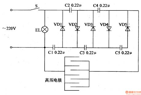
As seen in the 4-182, the citcuit consists of powering switch S, trap light EL, high voltage electrode, capacitor C1-C5 and diode VD1-VD5.
In the circuit, C1-C5 and VD1-VD5 make up a 5 times voltage rectification circuit.
When S is connected, EL is illuminated. 220V voltage will generate 1400V pulse voltage,which will be put onto the high voltage electrode. In the evening , when the pest touch the net, it will be killed by the high voltage.
(View)
View full Circuit Diagram | Comments | Reading(766)
Electronic Pest Killing Lamp (1)
Published:2011/5/20 3:53:00 Author:Sue | Keyword: Electronic, Pest, Killing, Lamp

In the daytime, IC's 6 pin has a high level, 3's pin has a low level and VF1 is disconnected. The whole circuit doesn't work. In the evening, IC1's 2 pin has a low level, 3 pin has a high level, and VF1 is connected. The circuit begins to work. When the multivibrator begins to work, IC2's 3 pin outputs oscillator signals. The signal will generate alternating current 220V voltage, illuminating EL. Another circuit will generate high voltage,which will be sent to the electronic net. (View)
View full Circuit Diagram | Comments | Reading(667)
Temperature Control Circuit Composed Of T-121 Temperatrue Sensor
Published:2011/5/22 0:48:00 Author:Robert | Keyword: Temperature, Control, Sensor
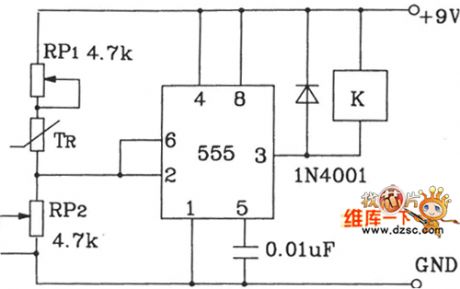
The controlled temperaturepoint can be set by adjusting RP1 and RP2. The 555 time-base circuit makes up the schmitt out-phase circuit. It uses the relays to achieve the equipment's automatical control. The T-121 temperature sensor makes the temperature control circuit which is shown below.
(View)
View full Circuit Diagram | Comments | Reading(925)
Standard Computer Interface Data Bus Circuit Composed Of LM35DZ Celsius Temperature Sensor And A/D Converter
Published:2011/5/22 3:56:00 Author:Robert | Keyword: Standard, Computer, Interface, Data Bus, Celsius, Temperature Sensor, A/D Converter
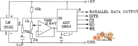
The Standard Computer Interface Data Bus Circuit Composed Of LM35DZ Celsius Temperature Sensor And A/D Converter is shown in the picture below.
(View)
View full Circuit Diagram | Comments | Reading(1201)
The circuit of ICL7103A high precision digital voltmeter
Published:2011/5/20 0:17:00 Author:Borg | Keyword: high precision, digital voltmeter
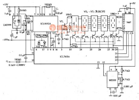
The figure is a circuit of ICL7103A high precision digital voltmeter. This circuit is a 4.5 bit digital voltmeter circuit. ICL8052A contains reference voltage, but the voltage can't meet the minimum need of long stability, therefore, it needs to connect a reference power supply of high temperature stability from outside, the voltage is formed by LM3999. There are some problems to notice when we are assemble the circuit: the analog spot and digital spot are completely separated, there is only a ground connection near the circuit; and when we print the design of the circuit board, the digital signal induction to the analog is to be noticed.
(View)
View full Circuit Diagram | Comments | Reading(3036)
Practical temperature controller circuit
Published:2011/5/13 0:59:00 Author:TaoXi | Keyword: Practical temperature controller
Practical temperature controller circuit (View)
View full Circuit Diagram | Comments | Reading(474)
555 vision care mndatory rest 10 minutes power supply socket circuit
Published:2011/5/23 8:01:00 Author:TaoXi | Keyword: vision care, mndatory rest, 10 minutes, power supply socket
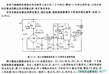
This power supply socket circuit is composed of the step-down rectifier circuit, the voltage-stabilizing circuit, the ultra-low frequency oscillator and the SCR control circuit.etc, as the figure 16-33 shows.
The step-down rectifier circuit outputs the +6V stable voltage. The ultra-low frequency astable multivibrator is composed of the IC2(555) and the R2,RP1,R3,C3. When you close the power supply switch SA, C3's charging voltage can not be mutated, so pin-2 has the low electric potential at the beginning to make the 555 in the setting state, and pin-3 outputs the high electric potential, the SCR conducts, the socket CZ gets the power to turn on the electrical equipments or lights.
(View)
View full Circuit Diagram | Comments | Reading(867)
555 amblyopia treatment rear shape therapy control circuit
Published:2011/5/23 6:30:00 Author:TaoXi | Keyword: amblyopia, treatment, rear shape therapy, control circuit
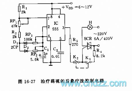
As the figure 16-27 shows, the astable multivibrator is composed of the 555 and R1,R2,RP1,RP2,RP3, the oscillation periods are:
T=tcharging+tdischargingtcharging=0.693(R1+RP1+R2+RP2)C1tdischarging=0.693(R2+RP1+RP2)C1
You can change the frequency and the duty ratio by adjusting the RP1,RP2,RP3, at the initial treatment, the frequency of 50 times per minute is better, then, you can improve the frequency to 70-80 times per minute. When the switch K2 cuts off, the light time is about 1 minute; when K1 cuts off, K2 opens, the treatment light will cyclical changes.
(View)
View full Circuit Diagram | Comments | Reading(572)
555 floodlight ultrasonic remote controller circuit
Published:2011/5/23 5:30:00 Author:TaoXi | Keyword: floodlight, ultrasonic, remote controller
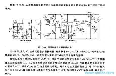
As the figure 17-39 shows, the controller is composed of the ultrasonic remote control circuit and the control circuit, and it can be used in the application of light remote control switch.
The astable multivibrator is composed of the 555 and the R1,RP1,C1, the oscillation frequency f=1.44/(R1+RP1)C1, by adjusting the RP1, we can keep the frequency between 40kHz+/-500Hz. The ultrasonic transmitter head uses the UCM40T piezoelectric sensor.
If we adjust the RP1 on the output frequency load, the LM567 input signal will be larger than 25mV, the output port pin-8 has the low electrical level, VT3 is saturation conduction, SCR is trigger conduction, the light turns on.
(View)
View full Circuit Diagram | Comments | Reading(618)
555 photo amplifier sequence controller circuit
Published:2011/5/23 4:19:00 Author:TaoXi | Keyword: photo amplifier, sequence controller
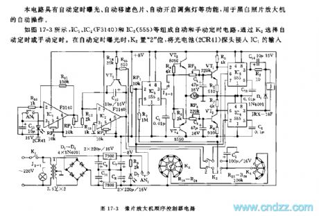
This circuit has the functions of automatic timing exposure, automatic shifting filter and focus light automatical turn-on, and it can be used in the automatic operation of the black and white photograph amplifier.
As the figure 17-3 shows, the automatic and manual timing circuit is composed of the IC2,IC2(F3140) and IC3(555), we can choose the automatic timing mode or the manual timing mode by K2. In automatic timing exposure process, K2 is in the position of 2 , we connnect the photocell (2CR41) probe to the IC1's input port, and adjust RP3 to make the IC2's pin-6 to output the level signal which is higher than 0V.
(View)
View full Circuit Diagram | Comments | Reading(951)
555 household electric hot compress humidity control circuit
Published:2011/5/23 19:47:00 Author:TaoXi | Keyword: household, electric, hot compress, humidity control
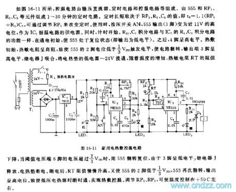
As the figure 16-11 shows, the temperature control circuit is composed of the regulated DC power supply, the timing circuit and the temperature control circuit.etc. The 1~30 minutes timing circuit is composed of the 555 and RP1,R5,C5.etc. The length of time depends on the values of RP1,R5 and C5. td=1.1(RP1+R5)C5, you can change the timing time by adjusting RP1. When you are using this circuit, press the switch AN, the 555 output (pin-3) becomes the 11V high potential as the power supply of the IC3 thermostatic circuit. At the same time, the timing begins. The R10,C7 integral circuits have the same function with the R4,C3 integral circuits of IC2.
(View)
View full Circuit Diagram | Comments | Reading(1255)
| Pages:260/312 At 20241242243244245246247248249250251252253254255256257258259260Under 20 |
Circuit Categories
power supply circuit
Amplifier Circuit
Basic Circuit
LED and Light Circuit
Sensor Circuit
Signal Processing
Electrical Equipment Circuit
Control Circuit
Remote Control Circuit
A/D-D/A Converter Circuit
Audio Circuit
Measuring and Test Circuit
Communication Circuit
Computer-Related Circuit
555 Circuit
Automotive Circuit
Repairing Circuit