
Index 261
Household appliances timing socket circuit
Published:2011/5/19 0:44:00 Author:TaoXi | Keyword: Household appliances, timing socket
Household appliances timing socket circuit (View)
View full Circuit Diagram | Comments | Reading(444)
Light control timing newspaper column light circuit
Published:2011/5/18 10:37:00 Author:TaoXi | Keyword: Light control, timing, newspaper column light
Light control timing newspaper column light circuit (View)
View full Circuit Diagram | Comments | Reading(441)
Light control timing advertising light circuit
Published:2011/5/18 10:34:00 Author:TaoXi | Keyword: Light control, timing, advertising light
Light control timing advertising light circuit (View)
View full Circuit Diagram | Comments | Reading(439)
Beijing Wuzhou elevator internal choice and floor indicating circuit
Published:2011/5/19 8:34:00 Author:TaoXi | Keyword: Beijing Wuzhou, elevator, internal choice, floor indicating
Beijing Wuzhou elevator internal choice and floor indicating circuit (View)
View full Circuit Diagram | Comments | Reading(395)
Beijing Wuzhou elevator power supply control circuit
Published:2011/5/19 8:35:00 Author:TaoXi | Keyword: Beijing Wuzhou, elevator, power supply, control circuit
Beijing Wuzhou elevator power supply control circuit (View)
View full Circuit Diagram | Comments | Reading(412)
Practical constant temperature controller circuit
Published:2011/5/13 0:59:00 Author:TaoXi | Keyword: Practical, constant temperature controller
Practical constant temperature controller circuit (View)
View full Circuit Diagram | Comments | Reading(472)
555 four words cycle neon light light control circuit
Published:2011/5/22 19:09:00 Author:TaoXi | Keyword: four words cycle, neon light, light control
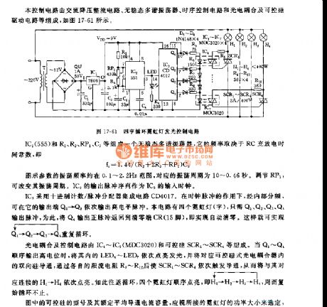
This control circuit is composed of the AC step-down rectifier circuit, the astable multivibrator, the timing control circuit, the optocoupler circuit and the SCR driving circuit.etc. As the figure 17-61 shows.
The astable multivibrator is composed of the IC2(555) and R2,R3,RP1,C3.etc. It's frequency depends on RC's charging and discharging time constant, f=1.44/(R2+2R3+RP1)C3.
The parameters of the figure's oscillation frequency is about 0.1~2.2Hz, the corresponding oscillation period is 10~0.46 seconds. By adjusting RP1, you can change the oscillation period.
(View)
View full Circuit Diagram | Comments | Reading(1431)
555 light control automatic flashing road-sign light circuit
Published:2011/5/22 7:32:00 Author:TaoXi | Keyword: light control, automatic flashing, road-sign light
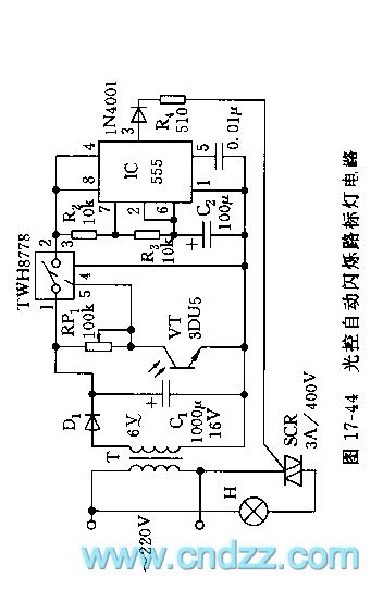
As the figure 17-44 shows, the circuit is composed of the transformer rectifier circuit, the light control switch and the 555 astable multivibrator.etc. The VT tube is the 3DU-type phototransistor, when there is the illumination, the port voltage of this transistor is less than 1.6V, the power switching tube TWH8778 cuts off because the control voltage of pin-5 is low, 555 has no power supply voltage. At night, the photodiode resistance increases, the circuit opens, the TWH8778 control port pin-5's voltage is higher than 1.6V, 555 get power to work, the oscillation frequency f=1/1.44(R2+R3)C2.
(View)
View full Circuit Diagram | Comments | Reading(882)
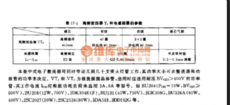
555 new high frequency fluorescent lamp circuit
Published:2011/5/22 19:42:00 Author:TaoXi | Keyword: new, high frequency, fluorescent lamp
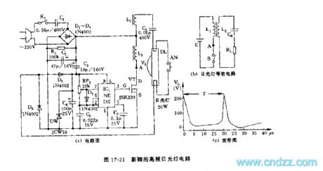
As the figure 17-21 shows, the high-frequency fluorescent lamp circuit is composed of the step-down rectifier circuit, the high-frequency oscillator circuit and the power driving stage.etc. This kind of light has no scintillation effect of the common fluorescent lamp (Working frequency is 50Hz), so it saves the ballast and starter.
The AC step-down circuit and the bridge type rectifier circuit supply the power supply voltage of VDD=+15V to the 555. The astable multivibrator is composed of the IC1(555) and RP1,D7,C5, f=1.44/RP1C5, the parameters of the figure has the oscillation frequency of 50kHz. IC1's output square wave drives the FET power transistor 2SK320.
(View)
View full Circuit Diagram | Comments | Reading(1342)
555 automatic exposure timer circuit (1)
Published:2011/5/22 20:06:00 Author:TaoXi | Keyword: automatic exposure, timer
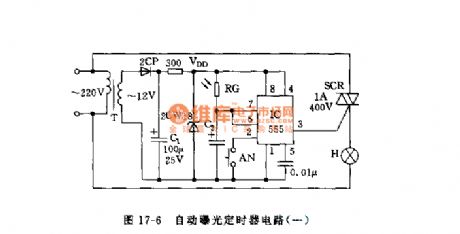
As the figure 17-6 shows, the circuit is composed of the step-down rectifier circuit and the 555 monostable circuit. The monostable circuit is composed of the 555 and photoconductive resistance RG, C2, when you press the button AN, 555 circuit sets, pin03 has the high electrical level to trigger the SCR, the expose lamp turns on. When the photoconductive resistance has no illumination, the resistance is so big, when the light turns on, the resistance of the photoconductive resistance reduces, the power supply charges C2 through the photoconductive resistance, when pin-6's voltage is higher than 2/3VDD, pin-3 has the low electrical level, SCR cuts off, the light turns off.
(View)
View full Circuit Diagram | Comments | Reading(790)
555 nighttime automatic bright showing light circuit
Published:2011/5/23 1:58:00 Author:TaoXi | Keyword: nighttime, automatic, bright showing, light circuit
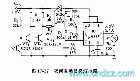
As the figure 17-37 shows, this circuit is composed of a photoelectric switch and a oscillator, it can be used to automatically show the signs and barriers.
The phototransistor VT1(3DU5) has the low resistance because of the illumination, VT2 cuts off, VT3 conducts, SCR cuts off because of the G port has the low electrical level, the indicating light turns off. At night, the c-e of the 3DU5 tube has the high resistance, VT2 conducts, VT3 cuts off, SCR conducts, and the IC starts working. The astable multivibrator is composed of the IC and RP1,R5,R6,C1, T=0.693(RP1+R5+R6)C1, the oscillation period is in the range of 2 to 10 seconds.
(View)
View full Circuit Diagram | Comments | Reading(572)
555 rock color light controller circuit
Published:2011/5/23 2:13:00 Author:TaoXi | Keyword: rock, color light, controller
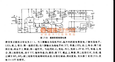
As the figure 17-56 shows, the controller is composed of the step-down rectifier circuit, the 555 multivibrator, the color light control circuit, and it can be used to parallelly control the 220V,5W small power color lights or series rock control the 6-12V small light bulbs.
The astable multivibrator is composed of the 555 and D3,D4,RP1,C2, by adjusting RP1, you can change the circuit's charging and discharging time constant to make the duty cycle of the alternating square wave to 2:1. When pin-3 outputs the low electrical level, the discharge tube of the substrate discharges, the pin-7 has the low electrical level, LED1 turns on, J1 closes, the first group of color lights turn on. Then this circuit goes round and round.
(View)
View full Circuit Diagram | Comments | Reading(668)
555 camera flash delay circuit
Published:2011/5/23 2:46:00 Author:TaoXi | Keyword: camera, flash, delay circuit
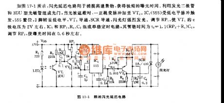
As the figure 17-1 showns, the camera flash delay circuit can be used to capture the high-speed scene, and you can get a very short exposure time. The light door is composed of the luminous diode and the 3DU type photosensitive tube. When the light is shadowed, the positive transition pulse adds to the VT2. The IC1(555) is triggered by the low-level pulse, 555 sets, pin-3 has the low electrical level, VT3 conducts, SCR conducts too. The monostable timing circuit is composed of the IC1 and RP2,R4,C2, the temporary stabilization time td=1.1(RP2+R4)C2.
(View)
View full Circuit Diagram | Comments | Reading(2065)
555 fluorescent group centralized rectification and start-up circuit
Published:2011/5/23 2:30:00 Author:TaoXi | Keyword: fluorescent group, centralized rectification, start-up circuit
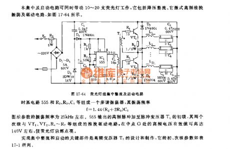
This centralized rectification and start-up circuit can drive 10-20 cigarettes of fluorescent lights to work. It is composed of the step-down rectifier circuit, the passive stimulating type high-frequency push-pull oscilation circuit and the driving circuit, as the figure 17-64 shows.
The multivibrator is composed of the time base 555 and the R2,R3,C3, the oscillation frequency f=1.44(R2+2R3)C3.
The parameters of the figure's oscillation frequency is about 25kHz. The high-frequency pulse which is output by 555 adds to the primary stage of pulse transformer T1, the push-pull driving circuit is composed of the two secondary stages and the VT1,VT2,R4~R7.etc.
(View)
View full Circuit Diagram | Comments | Reading(560)
555 practical DC stepless light modulator circuit
Published:2011/5/22 19:16:00 Author:TaoXi | Keyword: practical, DC, stepless, light modulator
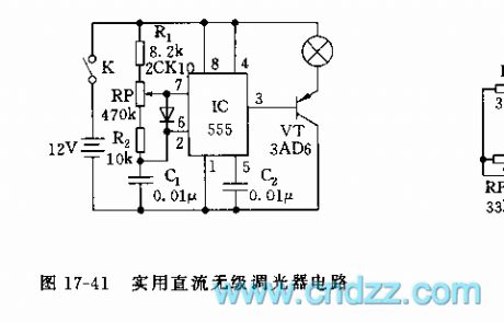
As the figure 17-41 shows, the light modulator uses 555 as the core. The astable multivibrator is composed of the 555 and R1,RP,R2,C1, the oscillation frequency f=1.44/(R1+RP+R2)C1, it is about 650Hz. The duty cycle range is from 4.5% to 95.5%, you can change the duty cycle by adjusting RP, so the brightness of light changes in a wide range, we realize the free dimming.
(View)
View full Circuit Diagram | Comments | Reading(581)
555 small electronic jewelry circuit
Published:2011/5/22 19:31:00 Author:TaoXi | Keyword: small electronic jewelry
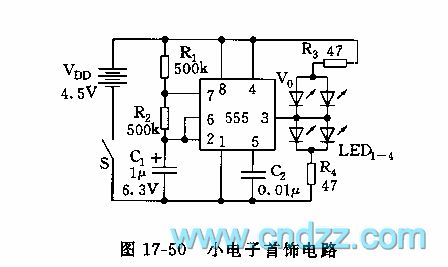
As the figure 17-50 shows, the small electronic jewelry is composed of the 555 and the luminotron.
The astable multivibrator is composed of the 555 and R1,R2,C1, the oscillation frequency f=1.44/(R1+2R2)C1, it is about 2Hz (it flashes twice per second). If the LED1~LED4 use different colors of LEDs, the effect is more better. R3,R4 are the current limiting resistor. (View)
View full Circuit Diagram | Comments | Reading(662)
555 automatic exposure timer circuit (2)
Published:2011/5/22 20:13:00 Author:TaoXi | Keyword: automatic exposure, timer circuit
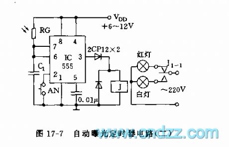
As the figure 17-7 shows, the monostable delay circuit is composed of the 555 and C1, cadmium sulfide photoresistor RG.etc. You install the RG near the photo, when exposure, if you press AN, 555 sets, J closes, the exposure light (white) turns on. If the illumination is strong, RG has the low resistance, td=1.1RGC1; if the illumination is weak, RG has the high resistance, td will be long. When the time of td is up, J releases, the white light turns off, the red light turns on, the exposure time complete.
Figure 17-7 The 555 automatic exposure timer circuit (2) (View)
View full Circuit Diagram | Comments | Reading(837)
555 music color light controller circuit
Published:2011/5/22 20:27:00 Author:TaoXi | Keyword: music, color light, controller
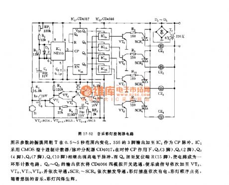
As the figure 17-52 shows, the controller is composed of the acousto-electric conversion circuit, the amplifier circuit, the clock pulse generator, the counter circuit and the control circuit. It controls the 4 channels of color lights to flash with the music.
The pickup microphone changes the music sound into the electric signal, and this signal adds to the 4 channels of analog switch IC3(CD4066). The astable multivibrator is composed of the 555 and RP1,R1,R2,D1,C1.
The parameters' oscillation period T is between 0.5~5 seconds. Pin-3's output of the 555 adds to IC2 as the CP pulse. IC2 uses the CMOS type decimal counter/pulse divider CD4017.
(View)
View full Circuit Diagram | Comments | Reading(1219)
555 emergency DC fluorescent lamp circuit
Published:2011/5/22 20:40:00 Author:TaoXi | Keyword: emergency, DC, fluorescent lamp
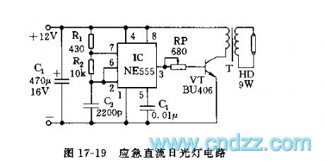
As the figure 17-19 shows, the astable multivibrator is composed of the 555 and R1,R2,C2, the oscillation frequency f=1.44/(R1+2R2)C2. The parameters of the figure have the high frequency oscillation frequency of 70kHz. The high-frequency square wave signal from the pin-3 is limited, then it adds to the VT tube, after the process of boost, this signal drives the light to turn on.
The transformer iron core uses the GU30X20 ferrite tank shape iron core.
(View)
View full Circuit Diagram | Comments | Reading(1752)
Beijing Wuzhou elevator control circuit (2)
Published:2011/5/19 8:36:00 Author:TaoXi | Keyword: Beijing Wuzhou, elevator, control circuit
Beijing Wuzhou elevator control circuit (2) (View)
View full Circuit Diagram | Comments | Reading(388)
| Pages:261/312 At 20261262263264265266267268269270271272273274275276277278279280Under 20 |
Circuit Categories
power supply circuit
Amplifier Circuit
Basic Circuit
LED and Light Circuit
Sensor Circuit
Signal Processing
Electrical Equipment Circuit
Control Circuit
Remote Control Circuit
A/D-D/A Converter Circuit
Audio Circuit
Measuring and Test Circuit
Communication Circuit
Computer-Related Circuit
555 Circuit
Automotive Circuit
Repairing Circuit