
Index 277
Peak value hold circuit diagram composed of TP0032
Published:2011/5/2 7:18:00 Author:Nicole | Keyword: Peak value
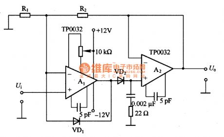
The figure of a peak value hold circuit composed of TP0032 is as shown. It is a high speed peak value hold circuit and isused to measure pulse. The biggest problem is the fidelity of narrow pulse. Although operational amplifier is very narrow, it also needs charging time when the diode charges to capacitance, so the width of measured pulse should not be too narrow.
(View)
View full Circuit Diagram | Comments | Reading(768)
Peak value hold circuit diagram composed of CA3130
Published:2011/5/2 7:08:00 Author:Nicole | Keyword: Peak value
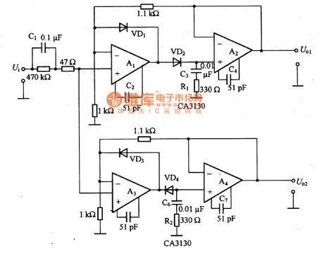
As shown in the figure, it is a peak value hold circuit which is composed of CA3130. This is a positive input, positive output and negative input, negative output circuit. If the output of negative peak value hold circuit is reversed by operational amplifier, then it will be the positive output circuit, do the same treatment to positive peak value. To change C3、R1 and C6、R2, it can make the output characteristic of pulse widths in frequency band flat. When A1 input is negative singal, VD1 turns on, it can prevent A1 ring working. As the same, VD3 is used to avoid A3 ring work. To add multiple negative feedback, it can reduce the nonlinear influence of VD2 and VD4.
(View)
View full Circuit Diagram | Comments | Reading(2298)
Infrared Control Electronic Ceremonial Speech Device Circuit Using TX05D
Published:2011/5/2 4:14:00 Author:Robert | Keyword: Infrared Control, Electronic Ceremonial Speech Device
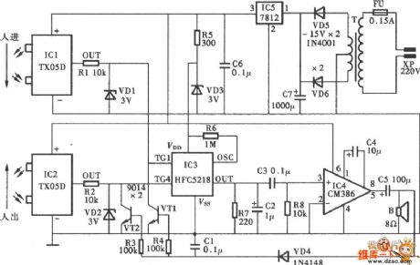
Infrared Control Electronic Ceremonial Speech Device Circuit Using TX05D is shown below:
(View)
View full Circuit Diagram | Comments | Reading(525)
Two-State Touch Light Control Circuit
Published:2011/4/30 19:53:00 Author:Robert | Keyword: Two-State Touch, Light Control
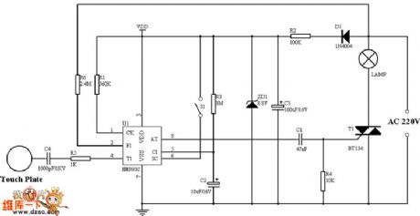
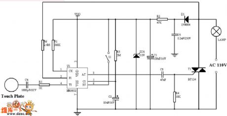
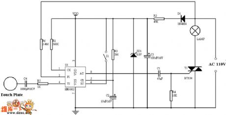
Picture (a) shows the 220V single-wire application circuit.
Picture (b) shows the 220V two-wire application circuit.
Picture (c) shows the 110V single-wire application circuit.
Picture (d) shows the 110V two-wire application circuit.
(View)
View full Circuit Diagram | Comments | Reading(2928)
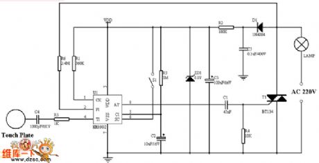
dimming table lamp circuit
Published:2011/5/2 9:12:00 Author:Christina | Keyword: dimming, table lamp
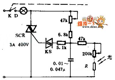
This table lamp can adjust the brightness, and the brightness will not change even if the grid voltage volatility surface changes.
Photosensitive resistor R can be installed on the lamp ornaments, it need the lamp's illumination.
(View)
View full Circuit Diagram | Comments | Reading(498)
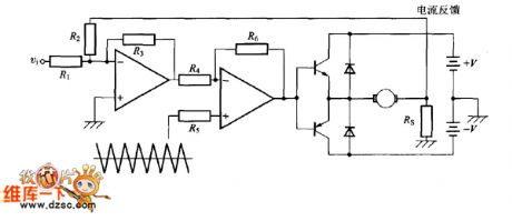
PWM Current Control Circuit
Published:2011/5/2 2:29:00 Author:Felicity | Keyword: PWM Current Control Circuit,
View full Circuit Diagram | Comments | Reading(973)
Infrared Control Water Faucet Circuit Using TX05D
Published:2011/5/1 10:04:00 Author:Robert | Keyword: Infrared Control, Water Faucet
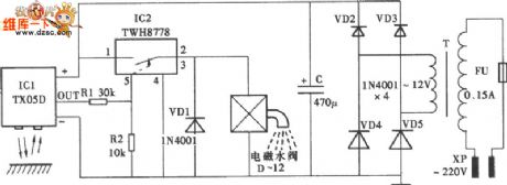
Infrared Control Water Faucet Circuit Using TX05D is shown below:
(View)
View full Circuit Diagram | Comments | Reading(1270)
Infrared Control Circuit
Published:2011/5/2 3:13:00 Author:Robert | Keyword: Infrared Control
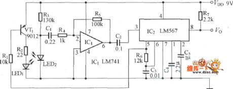
Infrared Control Circuit is shown below:
(View)
View full Circuit Diagram | Comments | Reading(557)
Infrared Control Electronic Dog Circuit Using TX05D
Published:2011/5/2 3:12:00 Author:Robert | Keyword: Infrared Control, Electronic Dog
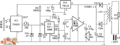
Infrared Control Electronic Dog Circuit Using TX05D is shown below:
(View)
View full Circuit Diagram | Comments | Reading(638)
Infrared Control Electronic Ceremonial Speech Device Circuit Using CX20106
Published:2011/5/2 4:06:00 Author:Robert | Keyword: Infrared Control, Electronic Ceremonial Speech Device
Infrared Control Electronic Ceremonial Speech Device Circuit Using CX20106 is shown below:
(View)
View full Circuit Diagram | Comments | Reading(699)
Pulse width modulation (PWM) DC motor speed controller circuit diagram
Published:2011/4/29 4:32:00 Author:Rebekka | Keyword: Pulse width modulation , DC motor , speed controller
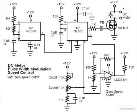
Pulse width modulation (PWM) DC motor speed controller circuit diagram. (View)
View full Circuit Diagram | Comments | Reading(5027)
Telephone calculagraph circuit diagram
Published:2011/4/29 3:54:00 Author:Rebekka | Keyword: Telephone calculagraph
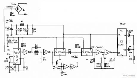
Call timer circuit is shown as below, phone timer uses 1 minute or 3 minutes for a timing unit. It starts automatically when the telephone is connected. It uses 10 LEDs jumping show the length of time. The timer circuit is simple, easy tuning. It is suitable for the electronic hobbyist. (View)
View full Circuit Diagram | Comments | Reading(879)
Hands-free phone voice-activated device circuit diagram
Published:2011/4/29 3:42:00 Author:Rebekka | Keyword: Hands-free phone , voice-activated device
Hands-free phone voice-activated device circuit diagram. (View)
View full Circuit Diagram | Comments | Reading(1140)
Temperature compensation circuit diagram composed of magnetosensitive resistance
Published:2011/4/29 3:24:00 Author:Nicole | Keyword: temperature compensation, magnetosensitive resistance
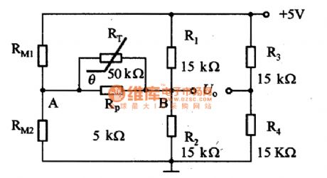
The figure 1 is a temperature compensation circuit which is composed of magnetosensitive resistance. In the circuit, the bridge connection is made of magnetosensitive resistance RM1 and RM2 and ordinary resistance R1, connecting a negative temperature coefficient thermal resistor RT between A-B. The coefficient adjustment resistance Rp is in parallel with RT, it can improve the temperature property of output U0. RT and Rp can select the best value according to RM1 and RM2.
(View)
View full Circuit Diagram | Comments | Reading(702)
Packet Control Circuit of Chandelier
Published:2011/4/21 9:39:00 Author:Christina | Keyword: Packet Control
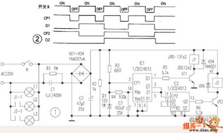
1.Operating Principle
The packet control circuit of chandelier is as Figure 1 shown, the function is as follows: when the power switch turned on, l1 group of lamp light; when the power switch turned on again, l1 and l2 group of lamp light; then the power switch still turned on, l1 and l3 group of lamp light; fourth operation, l1,l2 and l3 group of lamp light. If we continue to operate, the lanterns will be light over the order cycle again.
2.Installation
As the light control circuit is simple and has fewer components, we can make it into PCB before install it at the ceiling lamp's junction box. This circuit do not need to debug, just need to divide the chandelier lamps into three groups and connected correctly by this circuit. In the actual operation, you should avoid the voltage of c3 depleted.
(View)
View full Circuit Diagram | Comments | Reading(813)
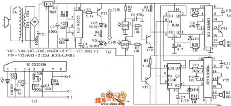
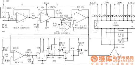
SE9518 multi-pattern program control color lamp control circuit
Published:2011/4/27 9:20:00 Author:Nicole | Keyword: program control, color lamp
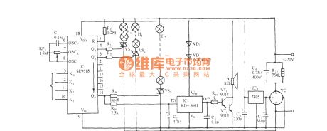
SE9518 is CMOS multi-pattern program control decorative color lamp special integrated circuit, it has eight-way drive output and through the different level grouping of pattern choice terminal K0,K1,K2,K3 can achieve more than 20 kinds of color lamp flashing and jump patterns. The circuit is as shown, it consists of eight-way color lamp control circuit, firecrackers sound, power amplifier circuit, AC depressurization rectifier circuit and steady voltage circuit. (View)
View full Circuit Diagram | Comments | Reading(560)
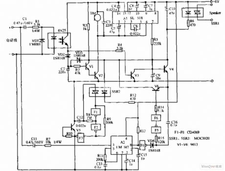
Control and alarm circuit diagram composed of SGZ07 sound and light alarm IC
Published:2011/4/28 22:59:00 Author:Ecco | Keyword: Control , alarm , sound , light, alarm IC
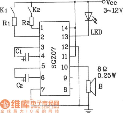
Control and alarm circuit diagram composed of SGZ07 sound and light alarm IC.
In the figure, the circuit can work in dual-band sound, light alarm circuit by controlling the K1, K2. If the R1, R2 in the circuit are changed in the corresponding thermal resistor (measured value), it can achieve temperature control and alarm circuit.
(View)
View full Circuit Diagram | Comments | Reading(899)
Mashgas, coal gas detection and alarm circuit
Published:2011/4/28 22:56:00 Author:Ecco | Keyword: Mashgas, coal gas, detection , alarm , monolithic, integrated circuit

Mashgas, coal gas detection and alarm circuit composed of CH217 monolithic gas detection alarm integrated circuit.
R1 in the figure is the gas sensing probe, the resistance reduces linearly with gas concentration arbitrarily increasing, RP3 is used to adjust the amplifier output, R6, R7 extract both forecasting and risk reference signal voltage.
(View)
View full Circuit Diagram | Comments | Reading(920)
Optical coupling silicon-controlled switch circuit diagram
Published:2011/3/30 22:58:00 Author:Ecco | Keyword: Optical coupling, silicon-controlled switch
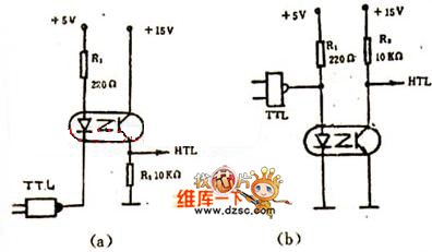

The figure 1(a) shows the optical coupling silicon-controlled switch circuitry. The trigger voltage of silicon-controlled rectifier(SCR) is from resistance R, and the the value is decided by the current of phototriode, controlled by input voltage. The circuitry is simple, and there is reliable electronic isolation between the input and output.
The figure 1(b) shows the switching circuitry in which load controll is pure resistance. And the value of R1 in the figure is decided by the formula as below: R1=V/1.2A,1.2A is bidirectional switching rated current. When the voltage of main network is 220V, V=/2·220=308V,then R1=308/1.2=250Ω. So the specification of silicon-controlled rectifier(SCR) is chosed according to the the value of R1.When the load of switching circuitry is inductive, it needs to increase corresponding components to promise the circuitry's normal work, as the current passing the inductive is different from the phase of voltage. It is shown as below: The switching circuitry shown in the figure 2 is especially suitable for distant control.
(View)
View full Circuit Diagram | Comments | Reading(1273)
Analog temperature controller circuit diagram
Published:2011/4/28 22:22:00 Author:Ecco | Keyword: Analog, temperature controller
View full Circuit Diagram | Comments | Reading(1164)
| Pages:277/312 At 20261262263264265266267268269270271272273274275276277278279280Under 20 |
Circuit Categories
power supply circuit
Amplifier Circuit
Basic Circuit
LED and Light Circuit
Sensor Circuit
Signal Processing
Electrical Equipment Circuit
Control Circuit
Remote Control Circuit
A/D-D/A Converter Circuit
Audio Circuit
Measuring and Test Circuit
Communication Circuit
Computer-Related Circuit
555 Circuit
Automotive Circuit
Repairing Circuit