
Index 265
Motor electronic governor controller 2
Published:2011/5/17 1:53:00 Author:Nicole | Keyword: motor, electronic governor, controller
The circuit work theory
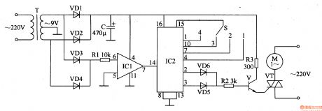
This motor electronic governor controller circuit is composed of power supply circuit, zero passage detection circuit and power regulating circuit, the circuit is shown in the figure 8-29.
The power supply circuit is made of power transformer T, rectifier diodes VD1, VD2 and filter capacitor C.
The zero passage detection circuit consists of diodes VD3, VD4, resistor R1 and operational amplifier integrated circuit IC1.
The power regulating circuit is composed of counter/distributor integrated circuit IC2, power adjustment switch S, diodes VD5, VD6, resistors R2, R3, transistor V and SCR VT.
(View)
View full Circuit Diagram | Comments | Reading(902)
Motor electronic governor controller 3
Published:2011/5/17 2:09:00 Author:Nicole | Keyword: motor, electronic governor, controller
The circuit work theory
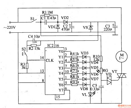
This motor electronic governor controller circuit is composed of power supply circuit, counter and optical control pulse width modulation circuit, the circuit is shown in the figure 8-60.
The power supply circuit is made of switch S1, depressurization capacitor C1, resistor R1, rectifier diodes VD1, VD2, steady voltage diode VS and filter capacitors C2, C3.
The optical control pulse width modulation circuit consists of resistors R4-R9, diodes VD3-VD8, LED VL, TRIAC VT, bidirectional trigger diode VD, light dependent resistor RG and resistor R10, capacitors C5.
(View)
View full Circuit Diagram | Comments | Reading(1824)
Electric oven control circuit with the AIRPAX67F temperature switch
Published:2011/5/13 1:20:00 Author:TaoXi | Keyword: Electric oven, control circuit, temperature switch
Related components PDF download:
VT66A
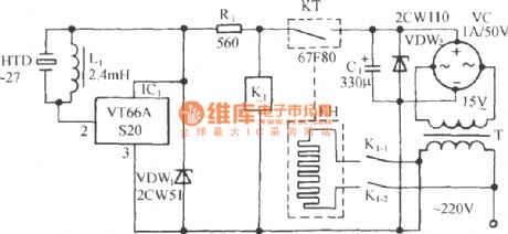
The circuit is as shown, it is composed of the temperature switch circuit, the stereo sound circuit and the AC step-down rectifier circuit.etc. You can install it on the electric oven or industrial oven to control the baking temperature in the given temperature range. AIRPAX67F is one kind of mechanical contact point solid switching device that can be used to detect the temperature and control the temperature, the contact point can control the temperature-control components (load current). (View)
View full Circuit Diagram | Comments | Reading(2800)
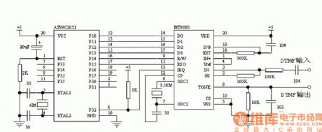
MT8880 Interface Circuit
Published:2011/5/16 9:12:00 Author:Michel | Keyword: Interface Circuit
View full Circuit Diagram | Comments | Reading(1934)
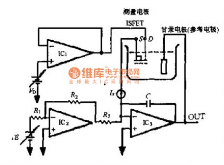
PH Meter Circuit
Published:2011/5/16 9:04:00 Author:Michel | Keyword: PH Meter, Circuit
View full Circuit Diagram | Comments | Reading(1462)
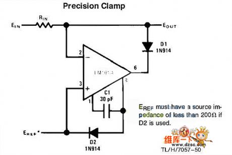
Clamp Circuit
Published:2011/5/16 21:07:00 Author:Sharon | Keyword: Clamp
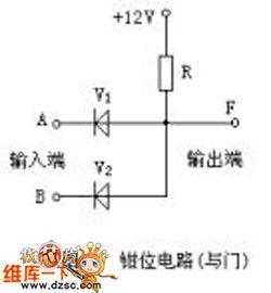
Clamp circuit is a circuit that clamps the output potential unchanged at a value. Clamp circuit working principle: Let the diode as ideal component, when the input UA = UB = 3V, the diode V1 and V2 are forward-bias conducted, and the output is clamped at UA and UB, ie, UF = 3V; when UA = 0V, UB = 3V, V1 is conducted, and the output is clamped at UF = UA = 0V, V2 is anti-bias cut-off. (View)
View full Circuit Diagram | Comments | Reading(589)
Outdoor light automatic control principle circuit
Published:2011/5/16 22:35:00 Author:Christina | Keyword: Outdoor light, automatic control, principle
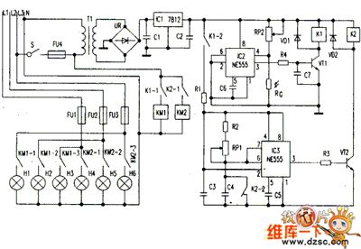
When you close the power switch S, the 220V city electricity gets to the transformer T1's primary stage through the fuse FU4, and the subprime output voltage (16V) is rectified by the rectifier bridge UR, then it gets through the regulator integrated block IC1, capacitance C1, C2's filters supply the operating power to the control circuit. IC2 and IC3 are the NE555 manifolds, the light control circuit is composed of the IC2 and the external components, the timing circuit is composed of the IC3 and the external components. The light is strong during the day time, so the photoresistor RG's resistance is small, the IC pin-24 reset terminal has the low-level voltage, transistor VT1 closes and the relay K1 cuts off, it's normally open contact points K1-1 and K1-2 cut off too, all the bulbs are not bright.
Figure: Outdoor light automatic control principle circuit (View)
View full Circuit Diagram | Comments | Reading(680)
Digital display host circuit
Published:2011/5/17 1:24:00 Author:Christina | Keyword: Digital display, host
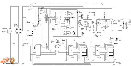
Figure: The Digital display host circuit (View)
View full Circuit Diagram | Comments | Reading(563)
Single chip hand washing controller circuit
Published:2011/5/16 19:37:00 Author:Christina | Keyword: Single chip, hand washing, controller
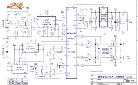
The sngle chip hand washing controller circuit is as shown:
(View)
View full Circuit Diagram | Comments | Reading(567)
OPA606 amp circuit
Published:2011/5/16 8:53:00 Author:Christina | Keyword: amp circuit
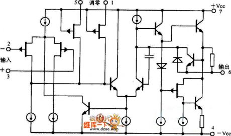
The OPA606 amp circuit is as shown:
(View)
View full Circuit Diagram | Comments | Reading(562)
Single power input/output amp circuit
Published:2011/5/16 4:31:00 Author:Christina | Keyword: Single power, input/output amp
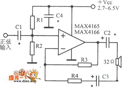
The Single power input/output amp circuit is as shown:
(View)
View full Circuit Diagram | Comments | Reading(418)
Zero drift amp circuit
Published:2011/5/16 4:26:00 Author:Christina | Keyword: Zero drift, amp
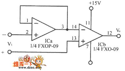
The Zero drift amp circuit is as shown:
(View)
View full Circuit Diagram | Comments | Reading(483)
Simplified motor sports photoelectric positioning control circuit diagram
Published:2011/5/17 1:21:00 Author:Ecco | Keyword: Simplified, motor sports , photoelectric positioning control
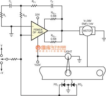
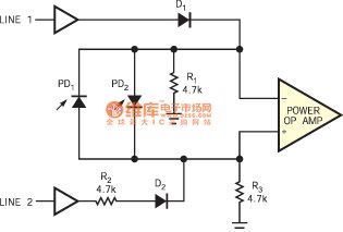
Figure 1 shows the circuit with the simple and basic design in order to achieve position control, it uses a pair of photodiodes connected in parallel with the the fast response time. Thus it achieves a system with small number of components, it has high reliability, accuracy and repeatability under clearly defined work environment. The circuit shown as the Figure 1 uses a power op amp to combine differential output of a pair of photodiodes, and it drives the direction of motor rotation to the right until the two photoelectric currents are equal, thus it achieves position control order.
(View)
View full Circuit Diagram | Comments | Reading(547)
Home Gas Safety Alarm Device Principle Circuit
Published:2011/5/16 9:29:00 Author:Robert | Keyword: Home, Gas, Safety, Alarm Device
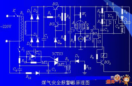
One part is the gas alarm device which would alarm before the gas density getting to the limit. The other part is a open negative ion generator whose function is generating air negative ion automatically. So the harmful ingredients carbon monoxide of the gas can react to the ozone (O3) in the air negative ion and this process produces harmless carbon dioxide.
The Home Gas Safety Alarm Device Principle Circuit is shown below.
(View)
View full Circuit Diagram | Comments | Reading(1252)
Temperature Control Circuit With Upper And Lower Limits
Published:2011/5/16 9:59:00 Author:Robert | Keyword: Upper And Lower Limits, Temperature, Control
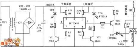
The Temperature Control Circuit With Upper And Lower Limits is shown below.
(View)
View full Circuit Diagram | Comments | Reading(818)
Optional frequency coefficient time delay circuit diagram
Published:2011/5/13 4:05:00 Author:Rebekka | Keyword: Optional frequency coefficient, time delay
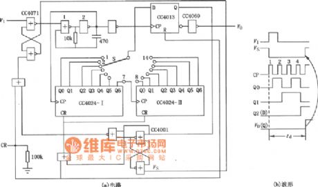
Optional frequency coefficient time delay circuit diagram is shown as above. The circuit is composed of two 7-bit binary serial counters CC4024, controlled pulse source (gate 1, 2 components) and input, output control circuit. (View)
View full Circuit Diagram | Comments | Reading(738)
Multifunctional Alarm
Published:2011/5/14 3:06:00 Author:Sue | Keyword: Multifunctional, Alarm
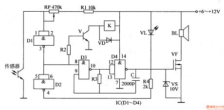
When the sensor detects nothing from outside, D1's input terminal is high level, while its output terminal is low level. D2 outputs high level, and VL is not illuminated. V is disconnected, and K is released. Audio oscillator composed of D3,D4,R3,C doesn't work and BL makes no sound.
When the sensor is stimulated, D1's input terminal turns into low level, and its output terminal becomes high level, which makes V begin to oscillate. The audio signal will force BL to make a warning sound after the signal is amplified by VF. (View)
View full Circuit Diagram | Comments | Reading(467)
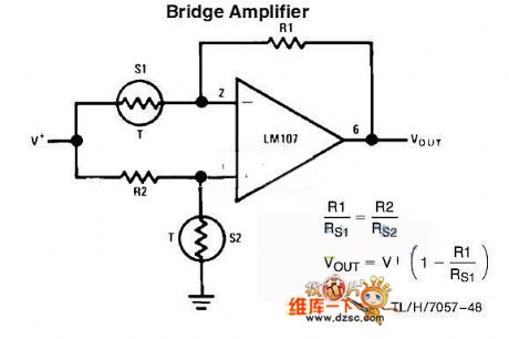
bridge amplifier circuit
Published:2011/5/16 3:12:00 Author:chopper | Keyword: bridge amplifier
View full Circuit Diagram | Comments | Reading(685)
exact clamper circuit
Published:2011/5/15 6:18:00 Author:chopper | Keyword: exact clamper
View full Circuit Diagram | Comments | Reading(1044)
Digital capacitance tester circuit
Published:2011/5/16 3:49:00 Author:Christina | Keyword: Digital, capacitance, tester
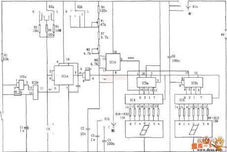
The Digital capacitance tester circuit is as shown. The tester is composed of the time base pulse generator, the monostable trigger, the addition counter, the decoder, the driver and the LED digital tube. And the time base pulse generator is composed of the IC1b (1/2 556) and R6, R7, R8, W1, W2, C2, it's output pulse signal can be used as the count pulse of the counting circuit (IC3). The monostable trigger is composed of the IC1a (1/2 556) and the R3 ~ R5, Cx (DUT capacitor).etc, the width of the output trigger pulse is td = 1.1 (R3 ~ R5) Cx, the greater the DUT capacitor is, the greater the timing width of the trigger pulse is, the counting of the corresponding counter IC3 are more. (View)
View full Circuit Diagram | Comments | Reading(1819)
| Pages:265/312 At 20261262263264265266267268269270271272273274275276277278279280Under 20 |
Circuit Categories
power supply circuit
Amplifier Circuit
Basic Circuit
LED and Light Circuit
Sensor Circuit
Signal Processing
Electrical Equipment Circuit
Control Circuit
Remote Control Circuit
A/D-D/A Converter Circuit
Audio Circuit
Measuring and Test Circuit
Communication Circuit
Computer-Related Circuit
555 Circuit
Automotive Circuit
Repairing Circuit