
Index 273
Radiation thermometer electricity testing temperature between 100-500℃
Published:2011/4/27 9:14:00 Author:Nicole | Keyword: Radiation thermometer, test temperature
This radiation thermometer uses lead sulfide photosensitive resistance 61SV as infrared radiation detector. In order to avoid the surrounding radiation mixing in measured value, so the measured radiationshould bemodulated by 350Hz frequency. Adopting filter which is composed of Ge or silicon to isolate the visible radiation.
When the voltage of photosensitive resistance is constant, and the temperature is in the range of 100~500℃, the singal value is changed about 1000 times. The total testing range is divided into 5 grades, using transfer switch S1 and S1' to choose.
The whole amplifier circuit is divided into 4 classes. Connecting a bridge rectifier circuit to last stage negative feedback amplifier to change the AC singal into DC singal. The measured value is displayed by moving coil meter(the measuring range is 200μA). (View)
View full Circuit Diagram | Comments | Reading(481)
Eight-way electric heater sequence delay switch control produced by 89C2051
Published:2011/4/22 19:17:00 Author:Nicole | Keyword: electric heater, switch control
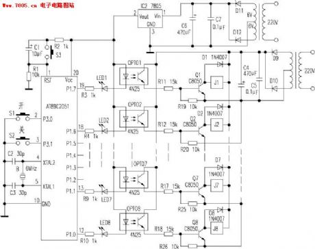
After energizing, 89C2051 resets, and P1.0 ~ P1.7 all the indicator lights off. P3.0 and P3.1are set to high level, to test whether there is start-up singal input in P3.0 port. When S1 is pressed, the start-up singal inputs P3.0 port, after avoiding flutter deal and confirmed by the program, the P1.0 port is set to low level immediately, LED8 lights, OPT08, Q8, J8 turn on, J8 normally open contact is closed, to turn on and control the AC contactor power supply of the first load electric water heater, the first load electric water heater starts working; after 10 seconds delay, the P1.1 port is set to low level, LED7 lights, OPT07, Q7, J7 turn on, J7 normally open contact is closed, to turn on and control the AC contactor power supply of the second load electric water heater, the second load electric water heater starts working; sothe power supply of the eighth load electric water heater is openedat last, thus, the electric water heaters from the first load to the eighth load are all in working condition. (View)
View full Circuit Diagram | Comments | Reading(1238)
Resistance-capacitance trigger unidirectional SCR dimming light circuit
Published:2011/5/5 7:33:00 Author:Nicole | Keyword: resistance-capacitance, unidirectional SCR, dimming light
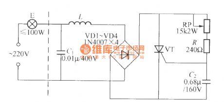
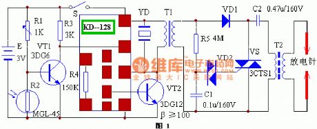
The circuit is as shown, it is a trigger unidirectional SCR dimming light circuit which is composed of resistance-capacitance components, 220V AC power supply is changed into DC pulse voltage by VD1~VD4 bridge rectifier, it is added to the anode and cathode of SCR VT. The trigger circuit consists of RP、R and C2, DC pulse voltage charges to capacitance C2 by RP、R, when it is charged to a value, SCR VT turns on, bulb E turns on and shines. When the pulse is added to the anode and cathode of VT is zero passage, VT automatically turns off, the power supply charges to C2 by RP、R, the circuit will repeat above operations. To adjust potentiometer RP, then it can change the charge rate of C2, so it can change the conduction angle of SCR VT, then the current effective value which flows bulb E will change, it can achieve stepless dimming's purpose. The feature of this circuit is low cost, the shortage of it: the voltage between the two poles of bulb will change in relation to temperature and input pressure. (View)
View full Circuit Diagram | Comments | Reading(1354)
Automatic delay light switch circuit
Published:2011/4/26 3:54:00 Author:Nicole | Keyword: light switch
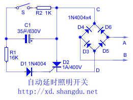
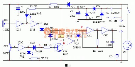
The working principle: the circuir is as shown. A, B are connected to the two terminals of switch. Closing switch S, the positive half cycle of AC will trigger SCR turn-on by D6、R2、R1、D1 and SCR control pole; the negative half cycle of AC by D4、R2、R1、D1 and SCR control pole will trigger SCR turn-on. After SCR turn-on, it is equal to short circuit C, D points, so A, B pointsare closed by diode and the turn-on SCR. The light is on.
After switch S off, the SCR still has trigger current and keep conductive, due to the capacitor C1 is discharging to it by R1, D1 and SCR control pole. The current is decreasing, after a few minutes, SCR off, then light goes out. The delay time is about 40~50s.
The component selection: to choose SCR with 1A maximum current, 400V voltage. 1N4004 can be used for D1、D3~D6. C1 adopts 630V, 35μF color capacitor. After closing switch S, the light is not on, you can decrease the resistance of R1 properly. (View)
View full Circuit Diagram | Comments | Reading(1094)
Novel touch switch table lamp circuit
Published:2011/5/5 7:35:00 Author:Nicole | Keyword: touch switch, table lamp

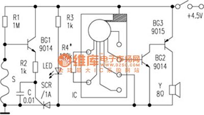
The circuit is as shown, it is divided into four grades to control the brightness of lamp. After connected to power supply, the light is not on, then you cantouch the lampshade metal shell for the first time. The bulb will emit low bright light. To touch it for the second time, the bulb will emit middle bright light, to touch it for the third time, the bulb will emit brightest light, to touch it for the fourth time, the bulb will off, as it order cycle. The prone failure of this circuit is TRIAC 97A6 breaks down and the poor contact between lampshade metal shell and circuit touch input terminal.
When I am debugging this circuit, using GS6061 to replace TT6061 and 1N4007 replace 1N4004, the other components are the same. It is proved that the circuit works well, it can achieve the functions as above. But TRIAC is easy to damage, so you can parallel a protection circuit which is composed of a series of resistence and capacitance on the two terminals of SCR. (View)
View full Circuit Diagram | Comments | Reading(1925)
Color lamp control circuit composed of SH808 multifunction music color lamp program control integrated circuit
Published:2011/5/5 7:36:00 Author:Nicole | Keyword: color lamp, program control
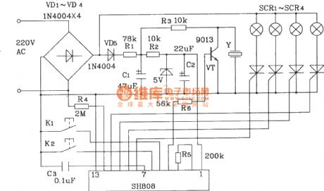
SH808 has music memory function, it can produce 16 songs and drive color lamp series, it will flash with music rhythm. Besides, the color lamp series will present racing horse jumping, chasing each other flashing, rolling waves and some flashing effects. These functions are divided into 8 program states: ①light series areall lighting without music. ②light series are flashing with music(repeat from 1~16 songs). ③light series are flashing with music(repeat from 1~4 songs). ④light series are flashing with music(repeat from 5~8 songs). ⑤light series are flashing with music(repeat from 9~12 songs).⑥light series are flashing with music(repeat from 3~16 songs). ⑦light series present racing horse jumping, chasing each other flashing, without music. ⑧light series present rolling waves, without music. (View)
View full Circuit Diagram | Comments | Reading(812)
WT8089 16 kinds of colored lamp patterns with eight pieces of music automatically control circuit
Published:2011/5/5 7:46:00 Author:Nicole | Keyword: color lamp pattern, music


The circuit is as shown. This circuit is composed as the core of WT8089, when it is playing a pretty electronic music, it can produce 16 kinds of different parrents dance methods. MODE terminal is actumatically controlled by clock pulse generator and the rhythm pulse is sent by shaping circuit, it can make the four kinds of color lamp control methods achieve automatical cycle and jumping. A low frequency pulse generator is composed of four 2 input terminal and the gate F1, F2 of negation gates IC CD4011 and resistor capacitor component, gates F3, F4 are connected to a RS trigger, it can trowel the waveform sent by oscillator, then it will change into standard square wave singal, it is added to MODE terminal (seven foot) of IC2, it can achieve automatical cxontrol for color lamp control method. The oscillation period of RC oscillator is
The oscillation period is adjusted in the range of 4~16s. To adjust RP1, it can coordinate color lamp's 16 kinds of changes and the rhythm of electronic music, good flashing jumping and feeling of music, the audio-visual effect is nice. (View)
View full Circuit Diagram | Comments | Reading(585)
Touch delay light circuit with time base circuit(1)
Published:2011/5/5 7:49:00 Author:Nicole | Keyword: Touch delay light, time base
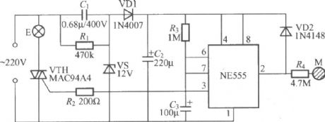
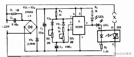
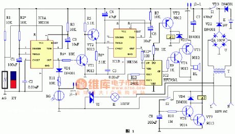
The figure is as shown, it adopts NE555 as core component to form the touch delay light circuit, the featureare precise delay time, good circuit repeatability. When you touch it one time, the light Ewill keeplighting about 150s. (View)
View full Circuit Diagram | Comments | Reading(1861)
Delay light circuit with time base circuit(1)
Published:2011/5/5 7:44:00 Author:Nicole | Keyword: Delay light, time base

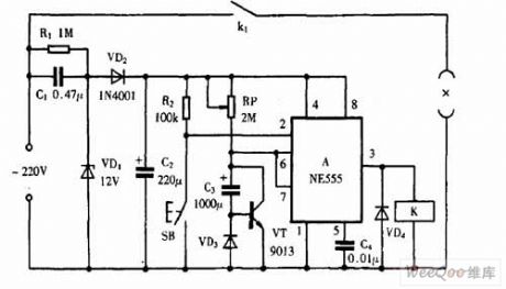
The figure is as shown, the NE555 is made as the core component to consist this delay light circuit. VD2, VS, C3, C4 form a simple diode rectifier steady voltage circuit, after connecting to power supply, the two terminals of C3 will output about 12V DC volgate to provide the whole circuit. NE555 time base circuit is connected into monostable working mode, C1 is full up charge, so NE555 threshold value or ⑥ foot is high level, time base circuit is in reset state, the ③ foot is low level, relay K has no action, light E offs. At this time, LED is lighting, it is used to indicate the switch position, it is convenient to find switch at night. (View)
View full Circuit Diagram | Comments | Reading(578)
Delay light circuit with time base circuit(2)
Published:2011/5/5 7:40:00 Author:Nicole | Keyword: Delay light, time base
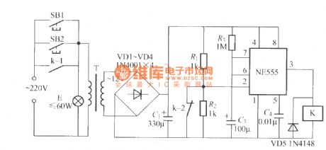
The figure is as shown, after turning off the light, the circuithas no power consumption. Relay K should use small electromagnetic relay with two groups of transfer contacts, such as JRX-13F、DC12V and so on. (View)
View full Circuit Diagram | Comments | Reading(481)
The circuit diagram of SH-804 festival multi-pattern color lamp with voice control function
Published:2011/5/5 7:39:00 Author:Nicole | Keyword: multi-pattern color lamp, voice control
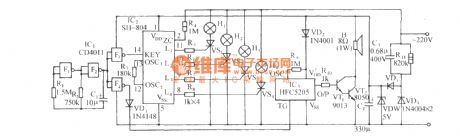

The circuit is as shown. It consists of clock beat generator, light control circuit, laughing phonation circuit and AC depressurization rectifier circuit. SH-804 is a CMOS color lamp program control special integrated circuit, it has ten kinds of circulation transform ways and six kinds of dimming light change speed such as up slowly fading, horse racing, jumping, smooth water, pour water, waves rolling, starsflashing and all brightness. The transform ways can automatically cycle changing, it also can artificial set flashing patterns through key terminal. This circuit adopts clock pulse automatic key way , to achieve the flashing patterns' automatic changing. F1~F4 is four 2 input terminal Nand, CMOS is IC CD4011, the F1, F2 and R2, C1 form a low frequency clock generator, the clock frequency is:
(View)
View full Circuit Diagram | Comments | Reading(643)
Isolating AC "weng" sound electro-optical isolating circuit
Published:2011/5/2 7:55:00 Author:Nicole | Keyword: AC, electro-optical isolating
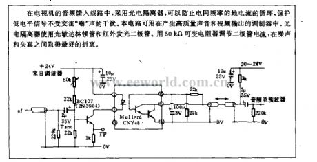
The TV audio feed-in circuit adopts photoelectric isolator to prevent grid frequency ground current from cycling, to protect low level singal from the interference of AC ong . This circuit is used in the modulator which can produce high quality sound and video output. The photoelectric isolator adopts photosensitive Darlington Transistor and infrared LED.It can use50kΩ variable resister to regulate diode current,then it will obtain best compromise between noise and distortion. (View)
View full Circuit Diagram | Comments | Reading(725)
Using NE555 Skillfully as On-off Time adjustable Cycle Timer Circuit
Published:2011/5/5 2:56:00 Author:Joyce | Keyword: Using NE555 Skillfully as, On-off Time, adjustable, Cycle Timer
Using NE555 Skillfully as On-off Time adjustable Cycle Timer Circuit (View)
View full Circuit Diagram | Comments | Reading(3872)
Using NE555 Skillfully as Long-playing Timer Circuit
Published:2011/5/5 2:56:00 Author:Joyce | Keyword: Using NE555 Skillfully as, Long-playing, Timer
Using NE555 Skillfully as Long-playing Timer Circuit (View)
View full Circuit Diagram | Comments | Reading(746)
LM317 steady voltage adjustable integrated circuit diagram
Published:2011/5/5 22:36:00 Author:Nicole | Keyword: steady voltage
LM317 is a integrated circuit with adjustable steady voltage which is produced by United States National Semiconductor Corporation, it is widely used in all kinds of electrical appliances power supply.
1, functions and features
LM317 integrated circuit contains steady voltage circuit, sampling voltage amplifier circuit, adjusting circuit and other assistant functions circuits.
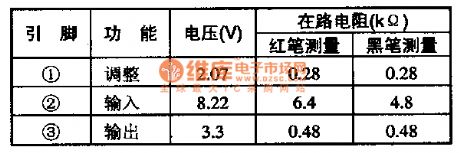
2, pin function and data
LM317 integrated circuit adopts 3-foot single line package, it is used in CHONG HONG precise display and precise display king back projection color TV, the integrated circuit's pin function and data is shown in the table1.
(View)
View full Circuit Diagram | Comments | Reading(546)
Smoke detection alarm circuit diagram
Published:2011/5/5 20:32:00 Author:Ecco | Keyword: Smoke , detection , alarm circuit
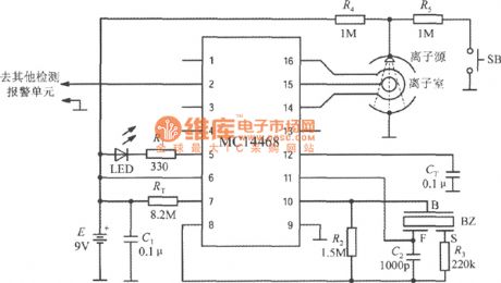
The smoke detection alarm circuit composed of MC14468 Ionic smoke detection alarm integrated circuit is shown as the chart. The device uses 9V laminated battery. RT and CT are respectively oscillation resistor and oscillation capacitor. LED is Light-emitting diode, R1 is the current limit resistor. BZ is the piezoelectric ceramic buzzer, which consists of three electrodes, namely B pole, F pole and S pole. Ion source is americium 241 (Am241), the radioactive intensity is as low as 0.8Ci (or 0.8 micro-Curie), and it will not cause harm to humans and pollute the environment. Ion source is installed at the top of the ion chamber. R4 and R5 are the partial pressure resistors. SB is self-test button. The source connects to +9 V voltage under normal state, when it is connected to SB, the voltage is +4.5 V, then it can simulate the case of detecting smoke. MC14468 can be connected to other test unit circuits through pin 2. (View)
View full Circuit Diagram | Comments | Reading(1476)
Micro-power break-type anti-theft alarm circuit
Published:2011/5/5 8:53:00 Author:TaoXi | Keyword: Micro-power, break-type, anti-theft alarm
The Micro-power break-type anti-theft alarm circuit is as shown:
(View)
View full Circuit Diagram | Comments | Reading(511)
voltage two-way over-restriction alarm protection circuit
Published:2011/5/5 8:38:00 Author:TaoXi | Keyword: voltage, two-way, over-restriction, alarm protection
The voltage two-way over-restriction alarm protection circuit is as shown:
(View)
View full Circuit Diagram | Comments | Reading(686)
Practical gate control anti-theft alarm circuit
Published:2011/5/5 8:23:00 Author:TaoXi | Keyword: Practical, gate contro, anti-theft, alarm
The practical gate control anti-theft alarm circuit is as shown:
(View)
View full Circuit Diagram | Comments | Reading(1287)
Automatic ignition gas blow-off alarm circuit
Published:2011/5/5 8:11:00 Author:TaoXi | Keyword: Automatic, ignition, gas, blow-off alarm
The Automatic ignition gas blow-off alarm circuit is as shown:
(View)
View full Circuit Diagram | Comments | Reading(1195)
| Pages:273/312 At 20261262263264265266267268269270271272273274275276277278279280Under 20 |
Circuit Categories
power supply circuit
Amplifier Circuit
Basic Circuit
LED and Light Circuit
Sensor Circuit
Signal Processing
Electrical Equipment Circuit
Control Circuit
Remote Control Circuit
A/D-D/A Converter Circuit
Audio Circuit
Measuring and Test Circuit
Communication Circuit
Computer-Related Circuit
555 Circuit
Automotive Circuit
Repairing Circuit