
Index 274
Thunder warning device circuit
Published:2011/5/5 7:54:00 Author:TaoXi | Keyword: Thunder, warning device
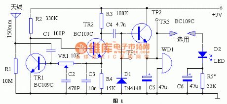
The Thunder warning device circuit is as shown:
(View)
View full Circuit Diagram | Comments | Reading(615)
Simple electric leakage alarm circuit
Published:2011/5/5 7:35:00 Author:TaoXi | Keyword: Simple, electric leakage, alarm
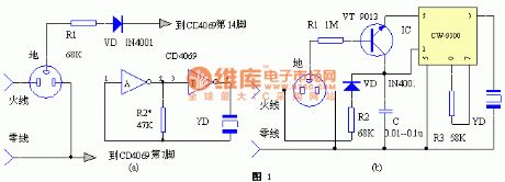
The Simple electric leakage alarm circuit is as shown:
(View)
View full Circuit Diagram | Comments | Reading(612)
multi-function alarm circuit composed of the wireless transceiver
Published:2011/5/5 8:58:00 Author:TaoXi | Keyword: multi-function, alarm, wireless transceiver
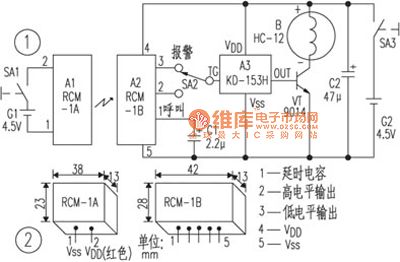
The multi-function alarm circuit composed of the wireless transceiver is as shown:
(View)
View full Circuit Diagram | Comments | Reading(555)
Simple multi-function alarm circuit
Published:2011/5/5 8:56:00 Author:TaoXi | Keyword: Simple, multi-function, alarm
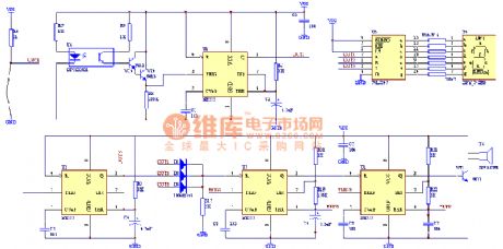
The Simple multi-function alarm circuit is as shown:
(View)
View full Circuit Diagram | Comments | Reading(562)
Door And Window Infrared Monitoring Anti-Theft Alarm Circuit
Published:2011/5/5 9:30:00 Author:Robert | Keyword: Door, Window, Infrared, Monitoring, Anti-Theft, Alarm
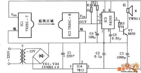
Door And Window Infrared Monitoring Anti-Theft Alarm Circuit is shown below:
(View)
View full Circuit Diagram | Comments | Reading(1776)
Automatic Hand Drying Controller Circuit
Published:2011/4/1 4:01:00 Author:may | Keyword: Automatic, Hand Drying Controller
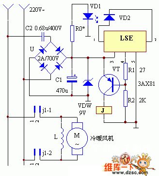
The operational principle of this circuit is shown in the diagram. Usually, the infrared rays emitted by the infrared emitting tube VD1 are exposed to the infrared receiver VD2, which leads the impedance of VD2 to decrease. At the same time, the fourth part of the LSE is outputing high electrical level, and the triode VT is at its deadline position. The electric relay J is in release condition with its normally open contact j 1-1 and j 1-2 disconnecting. The cold and warm air heating radiator can not work with no power supply. After people washing their hands, they will put their hands on the place between VD1 and VD2 where blocking out the infrared released from VD1, so the impedance of VD2 increases and the fourth part of LSE starts to output low electrical level, and the triode VT gets breakover, The electric relay J sucks close with its contacts power off. The cold and warm air heating radiator should be connected to power in advance and push the warm air button on the device.
(View)
View full Circuit Diagram | Comments | Reading(1300)
Super secret code lock circuit
Published:2011/5/5 3:26:00 Author:Christina | Keyword: Super, secret code, lock
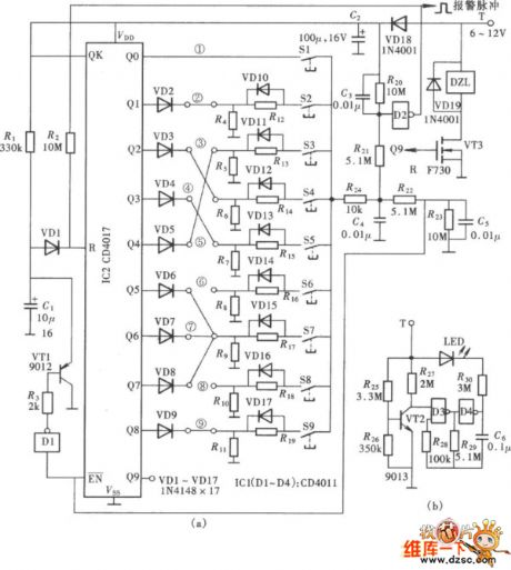
The super secret code lock circuit is as shown. This circuit is composed of the decimal counter CD4017's ten output ports, and the password group number is more than 100 million, so this lock can be called super-lock, the circuit is as shown. This circuit is simple, and is composed of a CD4017, 10 password input switches and other circuits.
Figure: Super secret code lock circuit (View)
View full Circuit Diagram | Comments | Reading(1203)
Driver alcohol detection alarm controller circuit
Published:2011/5/5 2:31:00 Author:Christina | Keyword: Driver, alcohol detection, alarm controller
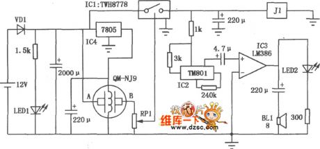
The driver alcohol detection alarm controller circuit is as shown in the figure. The QM-NJ9 is alcohol gas sensor, if it detects the alcohol odor, the resistance of QM-NJ9 between A and B will shrink, and the wiper potential of potentiometer RPl will rise up. When the voltage level is 1.6V, the ICl high-power switching device TWH8778 is connected to make the IC2 voice IC TM801 to work, the output is amplified by the IC3 integrated amplifier LM386, and then the amplified output drives the speaker BLl to send out alarm. Meanwhile, the relay J1 gets the power to start working, the contact point disconnects and cuts off the car ignition circuit to stop the engine, to achieve the purpose of control the drivers drink and drive.
(View)
View full Circuit Diagram | Comments | Reading(5511)
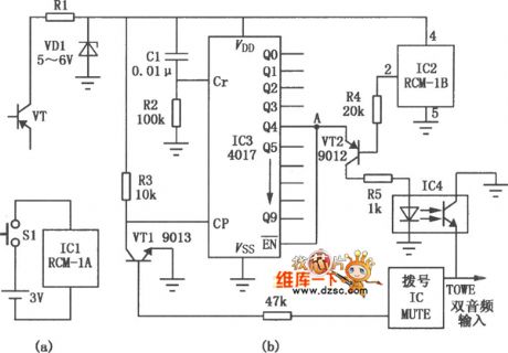
Long-distance call lock circuit
Published:2011/5/5 2:51:00 Author:Christina | Keyword: Long-distance, lock
The long-distance call lock circuit is as shown, it has the following features: if you want to make a long distance call (the first telephone number is zero), you need to enter the 4-digit password and hang up for 1 ~ 2s then you can make the long distance call; this circuit does not limits the non-long-distance calls (the first telephone number is not zero); you can set any passwords and limit to call the restricted number.
(View)
View full Circuit Diagram | Comments | Reading(641)
741 op-amp device as the I/V converter circuit
Published:2011/5/4 2:30:00 Author:Christina | Keyword: op-amp device, I/V converter
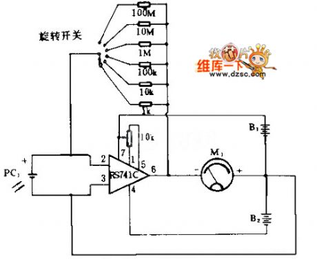
The 741 op-amp deviceas the I/V converter circuit is as shown. Current of PC1 can be considered that all through the feedback resistor, the current flowing through the ammeter equal to 741C output voltage divided by the internal resistance of meter, and this current has relationship with the solar cells current. by whirling the switch and inserting resistances with different values the circuit can provide 6 stages metering range. When you access the 100MΩ resistance profile, it has the highest sensitivity. Power meter's sensitivity is 0 to 1mA.
(View)
View full Circuit Diagram | Comments | Reading(2171)
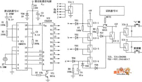
Automatic name-call telephone circuit
Published:2011/5/4 19:00:00 Author:Christina | Keyword: Automatic, name-call telephone

By this circuit, you can make the telephone call names automaticly, this means when the phone rings, this circuit will answer the phone automaticly, and ask who are you ? , if the opposite side people say: I'm looking for × × × × , the telephone will amplify the answer signal and send out the signal by speaker. This circuit is simple and reliable, and does not increase the load of communication network, you just need to change a line of the speaker. IC3 uses the 3 seconds language integrated circuit or the language processor. When you installing this circuit, you should keep the questioning speaker aim at or close to the machine microphone.
(View)
View full Circuit Diagram | Comments | Reading(856)
wireless remote control phone lock circuit
Published:2011/5/4 22:28:00 Author:Christina | Keyword: wireless, remote control, phone lock
The key of the telephone lock uses the remote controller form, the remote controller is in charge of the owner or office leader, the lock actuator is installed in the telephone. Only if you press the button on the remote controller, the lock will be opened and then you can dial. But the three numbers public phones such as the 119 , 110 , 120 .etc are not limited by this lock, also the answer. This circuit do not need the external power supply or mechanical lock, so it has some practical value.
(View)
View full Circuit Diagram | Comments | Reading(1175)
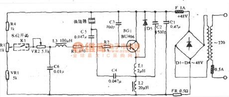
AC welding machine energy-saving controller circuit
Published:2011/5/4 22:29:00 Author:Christina | Keyword: AC, welding machine, energy-saving controller
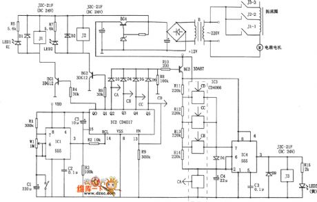
The AC welding machine has the intermittent working mode, the no-load power consumption in the interval can be several hundred watts. The AC welding machine energy-saving controller circuit is as shown. This circuit turns off the power in the interval, and turns on the power if you want to weld.
(View)
View full Circuit Diagram | Comments | Reading(6007)
KA9258-servo drive integrated circuit diagram
Published:2011/5/5 1:07:00 Author:Nicole | Keyword: servo drive

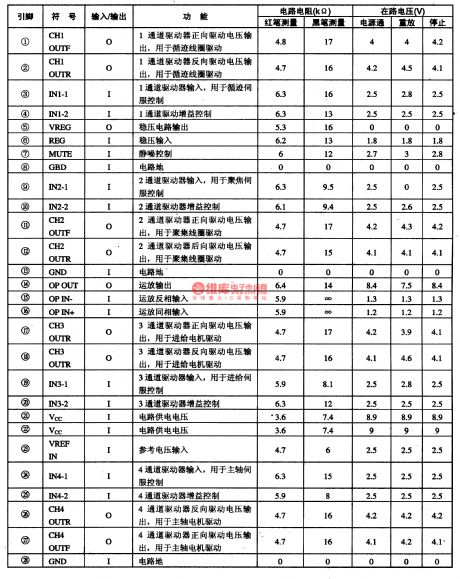
KA9258 is CD, VCD, SVCD, CVD player servo drive integrated circuit which is produced by South Korea's Samung.
1, internal circuit block diagram
KA9258 integrated block contains four-channel BTL drive circuit and drive squelch control circuit, it has the function of overheat protection. The internal circuit block diagram of this integrated block is shown as figure1-1.
2, pin function and data
KA9258D integrated circuit adopts 28-foot dual line flat type packing structure, the pin function and data of this integrated circuit is shown in chart1-1. This data is measured in VCD一21O VCD player.
(View)
View full Circuit Diagram | Comments | Reading(2058)
Pressure and temperature control system circuit diagram composed of VERSA
Published:2011/5/5 0:54:00 Author:Ecco | Keyword: Pressure, temperature, control system
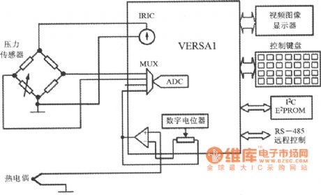
Pressure and temperature control system circuit diagram composed of VERSAmonolithic data acquisition system with DSP function
(View)
View full Circuit Diagram | Comments | Reading(910)
Temperature and gas concentration control system circuit diagram composed of VERSA1
Published:2011/5/5 0:56:00 Author:Ecco | Keyword: Temperature , gas , concentration , control system
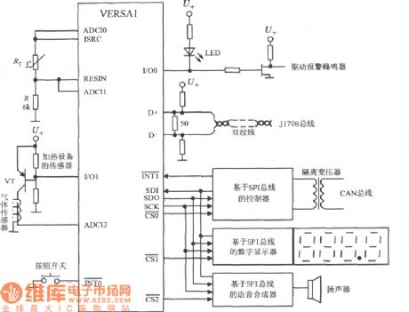
Temperature and gas concentration control system circuit diagram composed of VERSA1 monolithic data acquisition system with DSP function
(View)
View full Circuit Diagram | Comments | Reading(1069)
Yadu ultrasonic wave remote control switch circuit
Published:2011/5/4 9:30:00 Author:TaoXi | Keyword: Yadu, remote control, ultrasonic wave
The Yadu ultrasonic wave remote control switch circuit is as shown:
(View)
View full Circuit Diagram | Comments | Reading(498)
TC4052B, TC4052BP double 4 to 1 analog switch circuit
Published:2011/5/4 9:32:00 Author:TaoXi | Keyword: double 4 to 1, analog switch
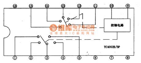
The TC4052B and TC4052BP is one kind of double 4 to 1 analog switch circuit which is produced by the TOSHIBA company, and they can be used in TV sound system, music center system and other systems as the multi-channel audio signal switcher.
1.TC4052B/BP circuit block diagram and pin functions
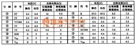
The TC4052B and TC4052BP has the same block diagram, as shown in figure 1, they are in the 16-pin double row package, the pin functions and data is as shown in table 1.
Figure 1. TC4052B/BP circuit block diagram and pin functions
Table 1. The pin functions and data of the TC4052B
2. TC4052B/BP typical application circuit
The typical application circuit of the TC4052BP is as shown in figure 2. It can be used in Changhong NC-3 Color TV's Kara OK circuit as the Kara OK mode switching typical application circuit.
Figure 2. TC4052B/BP typical application circuit
3.Circuit process
Add the signal R to pin ①, pin ②, pin (15) of the TC052BP, Signal L add to the pin-11, pin-12 and pin-4 of the TC052BP. Signal R outputs from pin-3 and signal L outputs from pin-13.
Relationship between the TC4052BP signal and Kara OK mode is as shown in table 2.
(View)
View full Circuit Diagram | Comments | Reading(7245)
photoelectricity control power supply socket circuit diagram
Published:2011/5/4 7:55:00 Author: | Keyword: photoelectricity, power supply socket
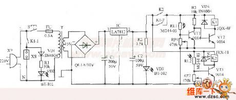
This set uses common flashlight beam as remote control instruction,making a conntrolled electric equipment socket, which is can control electric equipment socket power supply on/off in a few meters by touch flashlight switch conveniently.IC can use AN7812、LM7812、W7812 etc type interchangeably.Current amplification factor β of VT1~VT3 is about 200.RL1 and RL 2 can select MG44-03 type plastic resin encapsulation photosensitive resistant, or use other common photosensitive resistant that light resistant≤5kΩ,dark resistant ≥1MΩ instead.T is a 8W~10W power tranformer.
(View)
View full Circuit Diagram | Comments | Reading(1406)
Stepper Motor Working Timing Waveform Diagram
Published:2011/5/4 10:02:00 Author:Robert | Keyword: Stepper Motor, Working, Timing Waveform
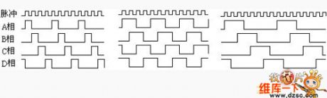
Stepper Motor Working Timing Waveform Diagram is shown below.
According tothe differences of the power turn-onorder of four-phase stepper motor, the working types could be divided into three types: singld four-beat, double four-beat and eight-beat. Single four-beat type's stepper angle is equal with the double four-beat, but single four-beat type's torque is little. Eight-beatworking type's stepper angle is half of the single and double four-beat type's. So, the eight-beat working type couldnot onlymaintain a high torque but also improve the control accuracy.
The single four-beat, double four-beat and eight-beat working type's power turn-on timing waveform diagrams are shown in the picture 2.a, b, c separately.
(View)
View full Circuit Diagram | Comments | Reading(2326)
| Pages:274/312 At 20261262263264265266267268269270271272273274275276277278279280Under 20 |
Circuit Categories
power supply circuit
Amplifier Circuit
Basic Circuit
LED and Light Circuit
Sensor Circuit
Signal Processing
Electrical Equipment Circuit
Control Circuit
Remote Control Circuit
A/D-D/A Converter Circuit
Audio Circuit
Measuring and Test Circuit
Communication Circuit
Computer-Related Circuit
555 Circuit
Automotive Circuit
Repairing Circuit