
Index 271
High voltage internal compensation op amp circuit
Published:2011/5/9 10:07:00 Author:Christina | Keyword: High voltage, internal compensation, op amp
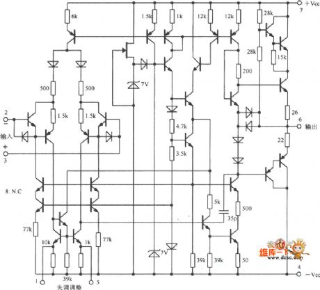
The High voltage internal compensation op amp circuit is as shown:
(View)
View full Circuit Diagram | Comments | Reading(2843)
CA3080 amplification circuit
Published:2011/5/9 8:04:00 Author:Christina | Keyword: amplification circuit
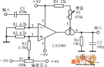
The CA3080 amplification circuit is as shown:
(View)
View full Circuit Diagram | Comments | Reading(1940)
side-channel filter circuit
Published:2011/5/9 7:57:00 Author:Christina | Keyword: side-channel, filter
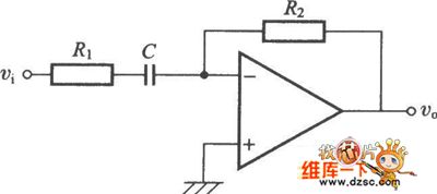
The side-channel filter circuit is as shown in the figure:
(View)
View full Circuit Diagram | Comments | Reading(462)
Simple Washing Machine Timer Circuit
Published:2011/5/9 19:15:00 Author:Robert | Keyword: Washing Machine, Timer
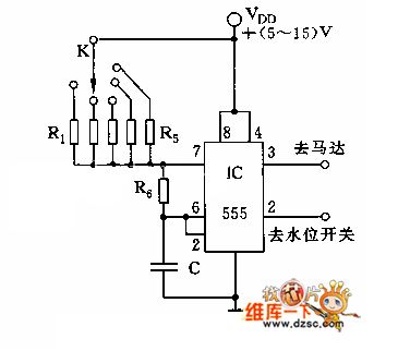
The Simple Washing Machine Timer Circuit is shown below.
(View)
View full Circuit Diagram | Comments | Reading(4017)
Low Power Consumption Window Temperature Detection Circuit
Published:2011/5/9 6:18:00 Author:Robert | Keyword: Low Power Consumption, Window, Temperature Detection
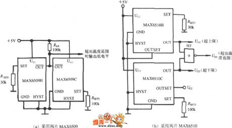
The Low Power Consumption Window Temperature Detection Circuit is shown below. (a) is using two MAX6509. (b) is using two MAX6510.
(View)
View full Circuit Diagram | Comments | Reading(575)
Intelligent temperature controller MAX6641 circuit diagram
Published:2011/5/10 1:33:00 Author:Nicole | Keyword: temperature controller

As shown in the figure, it uses PWMOUT terminal to drive N channel MOSFET, then to control the fan speed. remote PN junction temperature sensor can be replaced by the emitter junction of microprocessor (μP) internal temperature measurement triode. It also can adopt discrete component triode such as CMPT3906、T3906、KST3906-TF、SMBT3906 and other models. On the conditions of the highest prospective temperature and 10μA current, it requires the forward voltage drop of triode emitter junction should be higher than 0.25V ; on the conditions of the lowest prospective temperature and 100μA current, it should be lower than 0.95V. It should not use high power triode.
(View)
View full Circuit Diagram | Comments | Reading(609)
Constant temperature controller circuit diagram composed of intelligent temperature sensor LM75
Published:2011/5/9 22:55:00 Author:Nicole | Keyword: Constant temperature controller, intelligent temperature sensor
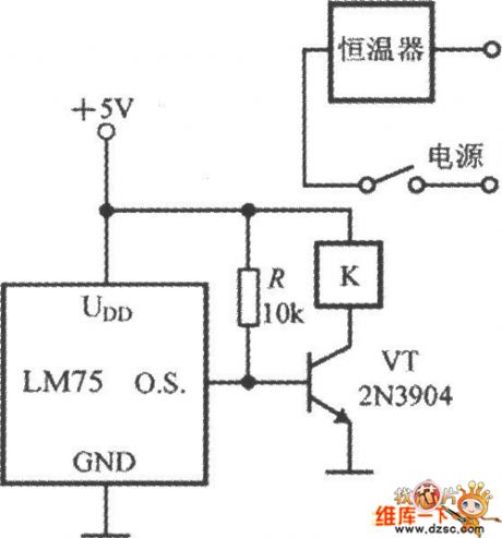
As shown in the figure, it is a simple constant temperature controller circuit which is based on intelligent temperature sensor of IC2 bus interface. LM75 drives relay coil K by 2N3904 transistor, it can control the thermostat power supply's on/off by the high and low of the measured environmental temperature, then it can achieve constant temperature control.
(View)
View full Circuit Diagram | Comments | Reading(1542)
4~20mA temperature transmitter circuit diagram composed of TMP35
Published:2011/5/10 4:02:00 Author:Nicole | Keyword: 4~20mA temperature transmitter
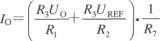
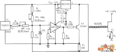
As shown in the figure, it is a 4~20mA temperature transmitter circuit which is composed of TMP35. This circut can change the voltage singal exported by TMP35 into 4~20mA standard current singal, it is used by automatic instruments to control the industry temperature. 4mA is as zero scale interval, 20mA is as full scale alue. REF193 is 3V reference voltage source, OP193 is operational amplifier, RP1、RP2 are calibration full scale alue and zero point's potentiometer, they can be adjusted independently. VD1 adopts Schottky diode, it can avoid OP193 open-loop voltage rising. The power voltage can be chosen between +9~+18V. The expression formula of transmitter's output current is:
(View)
View full Circuit Diagram | Comments | Reading(6838)
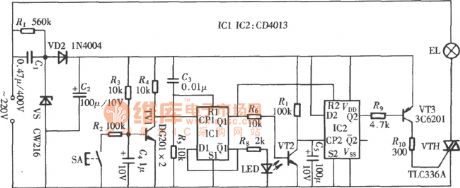
CD4013 feather-touch time delay switch circuit
Published:2011/5/10 1:52:00 Author:chopper | Keyword: feather-touch, time delay switch
View full Circuit Diagram | Comments | Reading(2047)
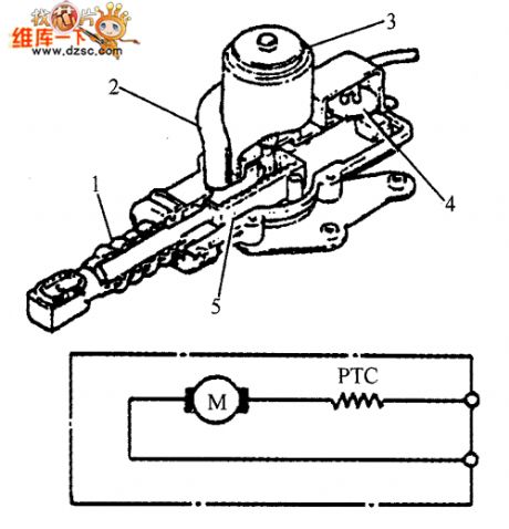
The structure and circuit diagram of gate control motor
Published:2011/5/9 21:09:00 Author:Nicole | Keyword: gate control, motor, structure
View full Circuit Diagram | Comments | Reading(529)
5-channel temperature measurement and control system circuit diagram
Published:2011/5/10 2:48:00 Author:Nicole | Keyword: temperature, measurement and control system

View full Circuit Diagram | Comments | Reading(812)
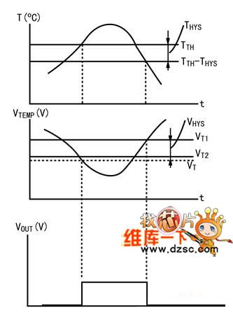
Temperature characteristic and output waveform circuit diagram
Published:2011/5/10 3:14:00 Author:Nicole | Keyword: temperature characteristic, output waveform
View full Circuit Diagram | Comments | Reading(469)
Constant temperature controller circuit diagram which is composed of AD7416
Published:2011/5/10 3:12:00 Author:Nicole | Keyword: Constant temperature, controller
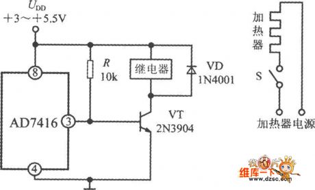
The constant temperature controller circuit which is composed of AD7416 is shown in the figure. AD7416 is set to low level and it works with comparison mode. When the temperature is lower than tHYST, AD7416 outputs high level, VT turns on, relay pulls in, the power supply of heater is turned on; when the temperature is higher than tOT1, VT turns off, relay gives off, the power supply of heater is cut off.
(View)
View full Circuit Diagram | Comments | Reading(558)
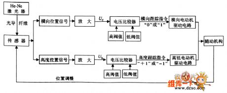
Switch laser upper phase tracking control route circuit diagram
Published:2011/5/10 3:29:00 Author:Nicole | Keyword: switch, laser, upper phase, tracking, control route
View full Circuit Diagram | Comments | Reading(559)
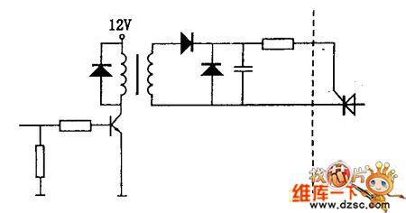
SCR drive circuit diagram
Published:2011/5/10 3:27:00 Author:Nicole | Keyword: SCR drive
View full Circuit Diagram | Comments | Reading(994)
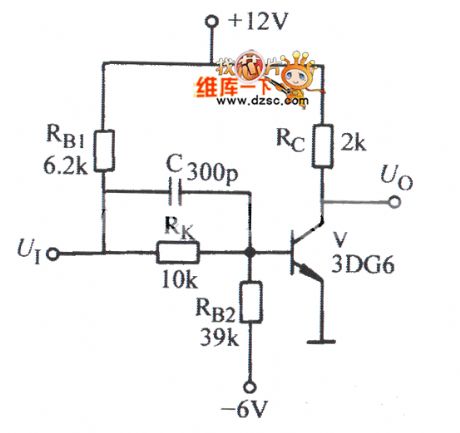
Transistor high speed switch circuit diagram
Published:2011/5/10 3:48:00 Author:Nicole | Keyword: transistor, high speed switch
View full Circuit Diagram | Comments | Reading(2220)
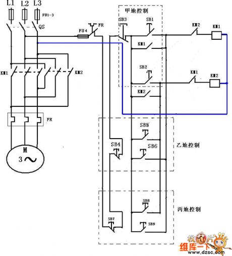
Three address control three phase motor positive inversion circuit diagram
Published:2011/5/9 22:07:00 Author:Nicole | Keyword: three addresscontrol, three phase motor, positive inversion
View full Circuit Diagram | Comments | Reading(668)
Bulb line fault display relay circuit diagram
Published:2011/5/9 21:35:00 Author:Nicole | Keyword: bulb line, fault display, relay
As shown in the figure, the relay is the sensor of detecting brake lamp, tail lamp filament off.
(View)
View full Circuit Diagram | Comments | Reading(523)
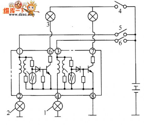
CC4052 multi-channel electronic switch integrated circuit diagram
Published:2011/5/9 2:24:00 Author: | Keyword: multi-channel electronic switch
CC4052 is a multi-channel electronic switch integrated circuits produced by Toshiba.It's widely used in audio, video, communications, car audio equipment and the signal switching switch in the other electronic devices.
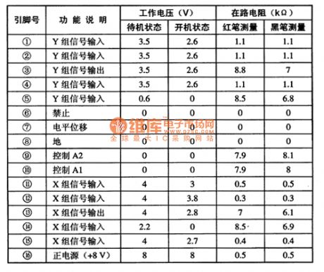
CC4052 integrated circuits use 16-pin dual in-line package.It is used on changhong CN一15 movement of large screen color TV.The pin functions and data listed in Table 1.
Table 1 CAT2404P integrated circuits' pin functions and data
(View)
View full Circuit Diagram | Comments | Reading(879)
Temperature control circuit of the rice cooker
Published:2011/5/9 20:33:00 Author:TaoXi | Keyword: Temperature control, rice cooker
The Temperature control circuit of the rice cooker (View)
View full Circuit Diagram | Comments | Reading(679)
| Pages:271/312 At 20261262263264265266267268269270271272273274275276277278279280Under 20 |
Circuit Categories
power supply circuit
Amplifier Circuit
Basic Circuit
LED and Light Circuit
Sensor Circuit
Signal Processing
Electrical Equipment Circuit
Control Circuit
Remote Control Circuit
A/D-D/A Converter Circuit
Audio Circuit
Measuring and Test Circuit
Communication Circuit
Computer-Related Circuit
555 Circuit
Automotive Circuit
Repairing Circuit